Thursday, August 30, 2012
How to install a 3G/4G cellular modem on my Android BeagleBoard setup
In this case, I used an Android Ultimate Pro Kit, which runs Android 2.3.4 on the BeagleBoard xM/BeagleTouch/BeagleJuice, 2nd Gen.
Note: There’s a much sleeker (beta) way to get cell modems running in Android with the new PPP widget from Draisberghof. I haven’t tried it out yet, and hooking up modems the old-fashioned way helped me learn a few useful tips and tricks in navigating ADB, so I’m writing it all out here. Enjoy!
Hardware I used
1 BeagleBoard xM
1 BeagleTouch
1 BeagleJuice, 2nd Gen (optional – a 5V power supply works fine too)
1 Android Ambrosia SD card
1 Linux or Mac computer (cygwin for Windows could also do the job, with a little bit of toolchain setup. I used a dedicated Ubuntu EeePC)
1 T-mobile Rocket 3.0 4G laptop stick (but most will work – see below)
1 Type B-mini USB cable for connecting the computer to Amber
Software I used
Android SDK with Android Debug Bridge
Linux terminal (Asus Eee PC is *perfect* for this)
This tutorial assumes that you already have Android SDK with Android Debug Bridge set up, and that you’re communicating to the BeagleBoard/Android device from a Terminal program.
Connecting your Android device
1. Switch on your BeagleJuice, 2nd Gen to power on the Android Ultimate Pro Kit.
2. Once the BeagleBoard is booted into Android, plug in a USB cable from the Linux terminal to the BeagleBoard’s OTG type B-mini port.
3. Open up Terminal in Linux.
4. I have the Android SDK and Android Platform Tools installed, so I can access Android Debug Bridge right from the prompt. The first thing I do is make sure my device is connected by typing:
adb devices
A list of connected and available Android devices should come up.
Tools you’ll need on the Android device
Most USB 3G/4G cellular modems are actually several “devices” rolled into one – the most notable being some form of onboard data storage.
USB_ModeSwitch is a fantastic utility that essentially does the heavy lifting of separating all these devices, so we can talk to the modem over USB serial directly.
5. Download and unzip the static binary for ARM processors: usb_modeswitch-1.1.9-arm-static.bz2
From your working directory, push the usb_modeswitch application to /system/xbin/ on your Android device:
adb push usb_modeswitch-1.1.9-arm-static /system/xbin/usb_modeswitch
6. Download the usbserial.ko kernel module from the Liquidware site. The reason I have it set up as a separate module is so that we can install usbserial as the driver for our modem, which is necessary to communicate. Then push usbserial.ko to your Android device:
adb push usbserial.ko usbserial.ko
This will put the usbserial.ko file in the root folder on your Android device, which is fine for our purposes.
We’ll create the usb_modeswitch config file you’ll need later.
Find your modem identification information
7. Go into Android shell:
adb shell
Now you can issue commands as if you’re in a terminal application on the Android device.
8. To see details about attached USB devices, first mount the usbfs file system.
mount -t usbfs usbfs /proc/bus/usb
Now type in:
cat /proc/bus/usb/devices
You should see a list of devices appear. Each USB device will have a Vendor ID and a Product ID. This detailed information also clues you in by telling you what Driver the USB device is currently using.
The one I’m looking for is the T-Mobile Rocket 4G, made by ZTE. Three relevant pieces of information:
Vendor=19d2
ProdID=2000
Driver=usb-storage
Each device has a vendor and product code identifier. The Driver is “usb-storage”, meaning that the composite modem is recognized as a USB mass storage device. Not very useful for our purposes. That’s where USB ModeSwitch comes in. You’ll tell USB ModeSwitch to send a special string of characters, which then splits the composite device into 6 independently communicating USB serial devices – one of which is our modem.
Write down your Vendor and Product ID, as well as your Manufacturer, Product, and SerialNumber info. These will all be helpful in finding the correct string that you’ll need to send to the modem via ModeSwitch.
7. In order for USB ModeSwitch to run properly, you’ll need to create USB modeswitch config file in the right format that has the correct string of characters. I started by looking on Draisberghof’s extensive list of device references. For the T-Mobile Rocket 4G 3.0 by ZTE, copy the following text into gedit on your Linux terminal, and create a file called usb_modeswitch.conf
########################################################
# ZTE devices
DefaultVendor= 0x19d2
DefaultProduct= 0x2000
TargetVendor= 0x19d2
TargetProductList="0001,0002,0015,0016,0017,0031,0037,0052,0055,0063,0064,0066,0091,0108,0117,0128,0157,2002,2003"
MessageContent="5553424312345678000000000000061e000000000000000000000000000000"
MessageContent2="5553424312345679000000000000061b000000020000000000000000000000"
MessageContent3="55534243123456702000000080000c85010101180101010101000000000000"
NeedResponse=1
CheckSuccess=20
8. Push usb_modeswitch.conf down to your Android device.
adb push usb_modeswitch.conf /system/xbin/usb_modeswitch.conf
9. There is one additional file you’ll need, which is known as a chat script. It secures the connection with T-Mobile. Open up gedit again and copy the following text, creating a file called dialtest.chat:
TIMEOUT 10
ABORT 'BUSY'
ABORT 'NO ANSWER'
ABORT 'ERROR'
SAY 'Starting GPRS connect script\n'
""'ATZ'
SAY 'Setting APN\n'
OK 'AT+CGDCONT=1,"IP","wap.voicestream.com"'
ABORT 'NO CARRIER'
SAY 'Dialing...\n'
OK 'ATD*99***1#'
CONNECT
10. Push the file down to your Android device:
adb push dialtest.chat dialtest.chat
This will put dialtest.chat into your root directory.
Turn on your 3G/4G cellular modem for Android
Now that all the right files are in the right places, we can execute all the commands at once.
11. Plug in your 3G/4G USB cellular modem. It should start blinking
12. Go into shell on your Android device:
adb shell
13. At the Android shell prompt, enter the following:
/system/xbin/usb_modeswitch -I -W -c usb_modeswitch.conf
The output will tell me whether the operation was successful, and if it was, you’ll see something like the above screenshot.
14. Notice that the “matching” vendor/product ID is 19d2:0157. We can now install the usbserial kernel directly to that device. Make sure you are in the root directory, since that’s where we put the kernel file. The vendor ID and product ID need to be written in hex.
insmod usbserial.ko vendor=0x19d2 product=0x0157
15. Now check to see what devices are attached to USB at this point:
cat /proc/bus/usb/devices
You should see something like the following:
Compare this to the original screenshot, where usb-storage was the only device and driver under this product.
If you’d like, you can check this under the list of serial devices by typing:
ls /dev/tty*
If you see ttyUSB0-5, you’re good to go!
16. This part usually takes a little experimenting to figure out which USB device you want to call with the pppd command. This is the correct one. It will execute the dialtest.chat script that you put on the device earlier. (If you’re looking closely, I put my dialtest.chat script in a different folder, but that’s not really a big issue as long as you have the right path)
pppd /dev/ttyUSB1 persist defaultroute usepeerdns -detach crtscts noauth debug connect "/system/xbin/chat -v -s -f dialtest.chat"
Be sure to leave this terminal window open to maintain the connection.
The above screen shot shows what happens on a successful initiation of the chat script. You are now ready to go online. ifconfig tells me what my network connections are. Note that ppp0 has an IP address, which means we’re connected to T-Mobile.
ifconfig
And the beautiful turquoise beacon, and CNN.com confirms that I’m online!
I’m sure there are going to be questions – email me at justin@liquidware.com or find me on twitter @liquidware. Or just comment below, and I’ll get back to you immediately.
Next up after the Labor Day Weekend, I’ll explain how to roll this all up into a boot script, so it can run instantly, every time you power on the Android device.
A big thanks to freedune for an excellent and well-written blog post, which steered me through most of this effort!
Wednesday, August 22, 2012
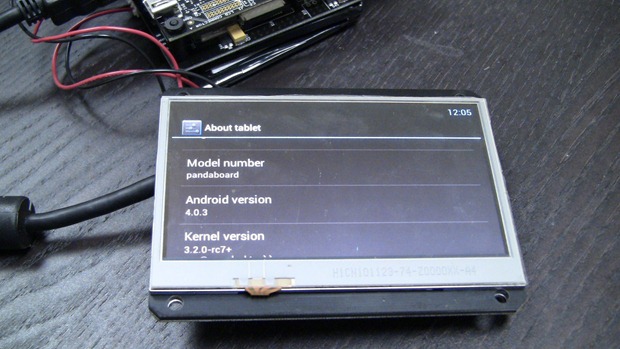
Introducing the Dual-Core Android 4 Dev Kit for PandaBoard
After quite a few months of requests, Chris and I got Android 4 running on the PandaBoard, along with an HDMI adapter board and some drivers to get the PandaBoard a “DIY tablet kit” of its own.
Just as the name suggests, the Dual-core Android 4 Dev Kit consists of the dual-core OMAP 4430 PandaBoard, Android 4 ICS (with Android serial support), 4.3” touchscreen enabled, powered by a laptop-grade battery pack, so it can be remote mounted, portable, or just permanently charging with a backup power supply.
The popular 4.3” BeagleTouch OLED display now works with the PandaBoard’s OMAP4430 with the help of a carrier board that conveniently brings the BeagleTouch pinouts to an HDMI connector.
The other side of the PandaBoard sandwich is the BeagleJuice, 2nd Generation, providing smart, laptop-grade battery and power management capabilities to the PandaBoard’s 5V input jack.
I don’t think that a few extra wires ever frightened any readers of this blog (if anything, there probably aren’t enough random wires on these boards!), but it’s fresh off the lab, so some of these extra wires are going to be solidified as the boards ship.
Either way, I’m pretty pumped about having a portable display + battery setup that works with the PandaBoard, but also one that runs Android 4 (ICS) and takes full advantage of Texas Instrument’s dual-core OMAP4430 processor.
One of the reasons I decided to make the panel remote mount capable (connected by wires rather than headers) is that the PandaBoard has a bigger footprint than the BeagleBoard, and a remote mount would allow the board and battery to be stored or mounted separately, much like most thin clients.
Here’s a quick demo I just put together:
Tuesday, August 14, 2012
Twittering shark laser intrusion detection system, in honor of Shark Week
I got an email from Dan earlier this week about making a fish tracking aquarium. Being that we’re right in the middle of Shark Week, I respectfully obliged…
This may or may not have implications for real-life shark tracking, but I’ll take an excuse to have my shark tweet me when he (or she, I’m no marine biologist) breaches the perimeter over to the sunny side of the tank.
Of course, I’m doing this with my toy shark-on-a-stick and only a laser level and a light sensor, but it’s possible to make this much more accurate and granular just by adding more strategically placed sensors/light sources into the mix.
Disclaimer: This project was designed purely with fun and proof-of-concept in mind, and in no way is designed to replace the $100 million airport intrusion detection system at JFK. The jet ski was too big and too fast for my 10 gallon fishtank…
because the lasers in Mission Impossible weren’t visible…
Concept
Most laser security systems rely on infrared sensors that detect changes in heat, based on a beam of light hitting the sensor. If that beam is interrupted, it’s interpreted as a change in the thermal profile on the sensor, and an alarm goes off. Usually the beams are invisible too, so that picture above is mildly inaccurate. Here’s the basic idea of how the project went:
I took a little field trip to Petco and Toys R Us to get a fish tank simulation setup. For the laser pointer, a laser light level I had in the shop worked really nicely, but any standard laser pointer will do.
Building the light sensor/laser setup
I ended up using a real, visible laser for two reasons: first, it’s easy to line up against my light sensor, and second, because I’m shooting the beam through water and 2 glass panels (on either side of my tank), which might otherwise diffuse the beam’s heat profile. Dry museums have it so easy…
On the other side of the tank, I have an Arduino with a light sensor elegantly taped to the glass.
I cut a hole in the wallpaper – on the left side, the laser is hitting the sensor directly. On the right, I moved the laser away, so you can see it the light sensor more clearly.
Chris and I just have some basic code running on the Arduino to get analog readings out from the AMBI light sensor. (The dead simple up-and-running post from way back when, as well as the wiki here). I uploaded the code to the Arduino, checked the output from serial, it seems like I’m good to go!
Connecting the sensor setup to a web-connected Android/BeagleBoard system
I connected the Arduino + Light Sensor to the BeagleBoard/BeagleTouch/Android stack sitting in my freshly dug up Mystery Box.
For a recap on how to connect the Arduino and sensor outputs over serial to output to the BeagleBoard over Android, here’s a link to the Antipasto wiki post. (This can still be tricky even with the Android Ambrosia SD card, so email me justin@liquidware.com, or comment below if you get stuck.)
Once I was able to get readings from the light sensor/Arduino in Android, I wrote a quick little Android APK to do two things:
1) Flash a Red Alert on BeagleTouch screenWhy Twitter? It’s excellent for posting event alerts in an easy to subscribe fashion, and it’s also really easy to have these alerts forwarded to SMS, email, and Facebook. And they have a pretty excellent API, which I’ll get to in the next section.
2) Trigger a tweet to be sent
If nothing is obstructing the the light sensor, the laser drives a light value of about 700-800.
As soon as the laser is obstructed by Bruce the shark himself, that light value drops. Once it’s below 400, the Android program issues a Red Alert warning that the sensor has been tripped, and sends a tweet.
This serial app, which Chris originally wrote for the Liquidware Amber, simply takes the values being sent from the Arduino/light sensor, then funnels it through the following logic:
A ratchet digital filter that detects when the sensor has been obstructed (and resets)
if ( (sensorVal < NIGHT_TRIP_POINT) && (ratchetCounter > ratchetMin))
ratchetCounter--;
if (ratchetCounter == ratchetMin)
time = NIGHT;
if ((sensorVal > DAY_TRIP_POINT) && (ratchetCounter < ratchetMax))
ratchetCounter++;
if (ratchetCounter == ratchetMax)
time = DAY;
Then here are a few of Bruce’s tweet alerts, stored in a String array:
String [] mTweets = {
"Yum.",
"Fish are friends, not food!",
"I am a nice shark, not a mindless eating machine.",
"Anchor! Chum!",
"So, what's a couple of bites like you doing out so late?"
};
Finally, bringing these two pieces together…
if ((time == NIGHT) && (prevTime == DAY)) {
mAlertDlg.setVisibility(View.V
ISIBLE);
Twitter Alerts from Bruce the Shark
Two of the world’s most famous sharks have been named Bruce (see hints below):
So I figured @BruceSharkAlert would be a fitting Twitter handle. In order to make Tweets actually happen, the code above needs to be linked to an authenticated Twitter developer account. Logging in as BruceSharkAlert on dev.twitter.com, this is what I’ve got:
I created this application…
Filled out the forms and got authentication keys…
(which I neatly chopped out :) They’re required in my Tweet.java file, which requires an authenticated account to automate tweet posts:
package com.liquidware.
networkedserial.app;
Phone Perimeter Breach Alerts
From there, I just followed @BruceSharkAlert, and since I have Twitter via SMS already set up, all I had to do was text 40404 (my Twitter “short code”) the command ON BruceSharkAlert. Now Bruce’s Tweets show up on my phone every time he breaks the laser line:
Mike gives us a little video walkthrough here:
When my phone goes off, I like to tell people that my shark tweeted me. Anyway, that’s my tribute to Shark Week, but if I had more time, laser pointers, and light sensors, I’d probably set up a crazy grid defense system. Till next time…
What else could I use this for? Let me know in the comments, over email at justin@liquidware.com or tweet me @liquidware
Monday, August 13, 2012
Recap: "Forever Sensor" at the RI Mini Maker Faire
During the faire, I had chance to explain the concept of the mystery box, and the rooster call it kept making. The younger and artistic audience really like the concept of a digital rooster, and the engineers truly appreciated the technical hurdles or the DIY perpetually-powered wireless environmental study project.
At first, the customized Android Tablet, 2 deep cycle marine batteries, the Arduino, the light sensor, the temperature/ humidity sensor, the solar panels and Pelican case seemed like overkill, but once I explained our reasons for the project, a lot of makers started having their own ideas on what they'd do with something like this.
Personally, this was my first time back to the Providence Maker Faire since 2009, but it was a lot of fun, and I can't wait for the Maker Faire in New York!
Thursday, August 9, 2012
How to build a DIY perpetually-powered wireless outpost
Earlier this week, I had a mystery box of electronics and was looking for something to do with it. Thanks to Bryan from New Zealand, who asked about creating a wireless farm monitoring outpost…
The idea of a perpetual power supply comes up now and again, mostly in the context of a remote outpost. Naturally, the idea of creating mesh networks in the wild and digital dead drops appeal to my inner Bourne, but that’s a story for a different day.
This project is really broken out into two parts: the perpetual powering, and then doing something useful with the perpetual power.
Perpetual (Self-Replenishing) Power
I found a couple of Mike’s old boat motor batteries, along with some 12V solar panels we had here in the lab. Since the batteries were 24V, I put the solar panels in series. Some back of the envelope math, along with my handy voltmeter, suggested that the solar panels could charge the batteries at about 200 mAH outside in the sun.
For the month of August, here in the Boston area, I get about 13.5 hours of sunlight. That means, each day, I’m storing about +2700 mA per day.
Testing the system that I have in the mystery box (which I’ll get to in a second), I’m burning a low of -75 mAH and a high of –150 mAH. It averages out to be about –100 mAH, or –2400 mA per day, for a net of +300 mA per day.
The massive batteries ensure that things will keep going for a while, even if I’m wrong about how much sun is getting through, and if there happens to be an unexpected volcanic cloud over Boston that day.
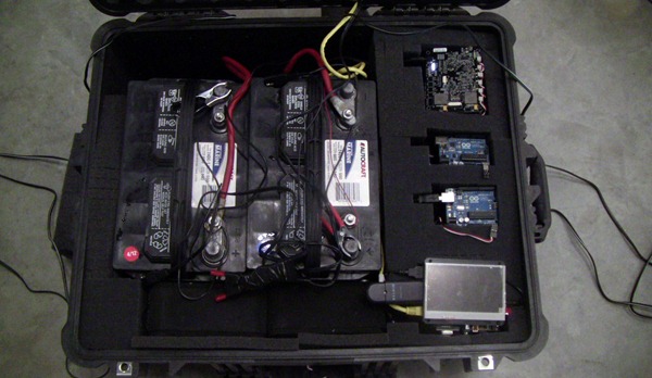
The Mystery Box (a.k.a. awesome Pelican case o’ stuff)
I put the batteries in the box, along with a BeagleBoard xM, BeagleJuice 2nd Gen, and BeagleTouch, as well as a couple Arduinos to run sensors.
The Pelican case itself is designed to be waterproof, although I hacked the neoprene o-ring in the front to run wires out of a single location. For testing purposes, I have a light sensor hooked up to the Arduino, and I have an AT&T 3G setup running from the BeagleBoard, which is sharing that Internet connection over WiFi to create a wireless hotspot. (If you look carefully at the top, I stuffed a wireless router in there as well)
There are three key links here, which each deserve a separate blog post complete with code:
Light Sensor to Arduino
Arduino with Sensor to BeagleBoard
BeagleBoard to 3G (I’ll write a blog about how to do this as well, but Dune made an excellent post, which got me started)
Towards the bottom, I also included a couple USB-powered speakers… (Oh the possibilities! :-)
Matt helped me dig a hole in the ground to bury the case, and then we ran some of the wires through a PVC contraption we made to mount the solar panels and WiFi antenna. It’s not the neatest thing in the world, but it works.
I’ve built a (mostly) perpetually-powered outpost, using a Pelican case, solar panels, some boat batteries, and an Android-powered BeagleBoard setup that converts a 3G cellular connection into a WiFi hotspot, all while logging and uploading sensor data. Now all I need is a coffee maker, and I’ll basically have Starbucks!
Naturally Mike had a brilliant idea for a light sensor and speakers…after all, what farm outpost would be complete without a rooster’s cockadoodledoo every morning. So I present to you, Mike’s Digital Cock app :-)
Next week, I’ll break out each piece of the project into distinct tutorials, especially the 3G cellular modem + BeagleBoard + Android component, which quite a few folks have been asking about.
What would you do with a remote, perpetually-powered wireless outpost? I’m planning to save this one for Halloween to have a robotic, motion-detecting scarecrow…
Post your thoughts to comments, or get a hold of me on twitter @liquidware, or over email at justin.huynh@liquidware.com
Wednesday, August 8, 2012
Powering my Raspberry Pi with the BeagleJuice, 2nd Gen Battery
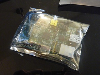
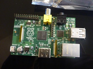
My Raspberry Pi finally showed up today! Naturally, an unboxing event was in order…
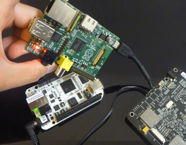
I haven’t gotten around to setting up my SD card yet, but I just wanted to see if it would power on with the BeagleJuice sitting on my desk. In theory, it should work, since the BeagleJuice outputs 5V from each of the 2-pin molex connectors.
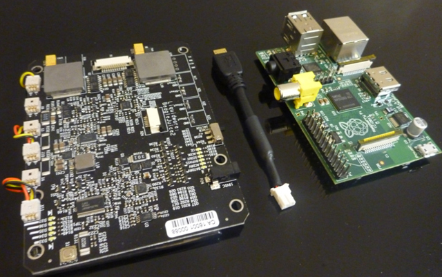
I took the micro USB cable that I spliced last week and plugged it into the Raspberry Pi…
…then I connected the other end to the BeagleJuice.
And voila! The Raspberry Pi powers on, as indicated by the red power LED next to the audio jack. Just for kicks, I plugged in the BeagleBone to the BeagleJuice as well (with a 5V barrel jack) to make sure they both run simultaneously, and they do :-)