Thursday, February 25, 2010

Introducing the Crash Test Sensor: CrashDuino, Analog Edition

The Crash Test Sensor is the newest sensor from the Liquidware and Modern Device joint engineering project.

Most handheld gadgets today have accelerometers, like my camera, which helps the camera detect whether I’m holding it portrait or landscape. The iPod Touch took it to a new level by adding a degree of sensitivity to orientation, which is pretty neat.

So Paul and I thought about what another level of accelerometer would look like, and we stumbled across the neat little ADXL278 chip from Analog Devices. It’s a dual-axis “high-g” accelerometer, which means that it can pick up on a much higher acceleration than the chip inside my camera that tells me which way my picture is facing. Like the acceleration just before impact if I threw my camera at a brick wall. Scientists use it test what kinds of injuries occur at what rates of acceleration- much like with crash test dummies.

Crash test dummies are actually much more complex than your average mannequin. They mimic average weight distributions of the human body, and there’s an entire field devoted to creating such anthropomorphic test devices.

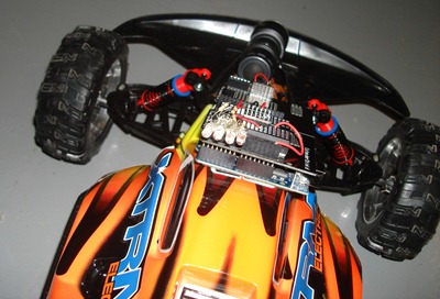
I wasn’t in the mood to create an actual crash test dummy, and I’ve been looking for an excuse to play with RC cars again, so I put together an analog crash test sensing rig that lights up depending on degree of impact, and started running it into things :)

Step 0: Assemble the Crash Test Sensor

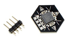
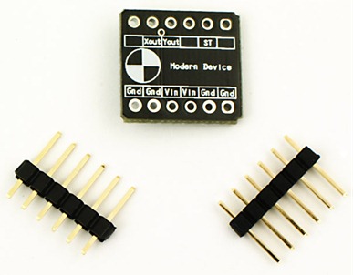
The Crash Test Sensor itself reads Xout, Yout, has a pin for self-test, and multiple pins to wire in Vin and Ground. It comes as a kit with two 6-pin male headers, which are pretty quick to solder up.SONY DSCStep 1:  Build CrashDuino Analog Arduino Crash Rig
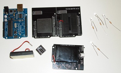
The “CrashDuino” rig consists of 4 white LEDs, which I soldered a 470 ohm resistor onto (to keep it fairly bright).

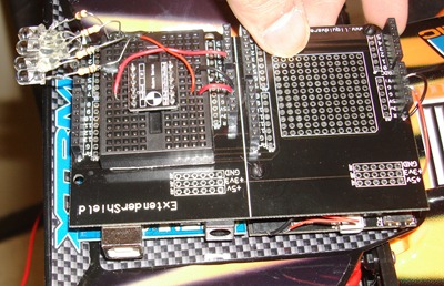
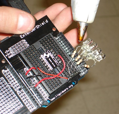
I then mounted the assembled Crash Test Sensor on a mini protoboard, which I stuck onto a DoubleWide ExtenderShield. I lined up the 4 LEDs to be controlled by Arduino digital pins, with the pins serving as Ground (or digital LOW) for the lights to go on.
Here’s the CrashDuino rig with LEDs while I hot glued the leads in place:
Step 2: Write CrashDuino Impact Test Code

I wrote some code to take an analog read of Analog Pin 0, where I had the Xout linked, and if that value hit a certain threshold, one of the LEDs in sequence would light up. If impact was strong enough to pass the next threshold, the next level LED would light up, and so forth until there was a crash that had impact high enough to trigger all 4 LEDs.

#define TP1 518
#define TP2 519
#define TP3 521
#define TP4 522
#define TP5 523

#define DELAY 750

void setup() {
pinMode(2, OUTPUT);
pinMode(3, OUTPUT);
pinMode(4, OUTPUT);
pinMode(5, OUTPUT);

digitalWrite(2, HIGH);
digitalWrite(3, HIGH);
digitalWrite(4, HIGH);
digitalWrite(5, HIGH);

Serial.begin(115200);

}

int value;

void loop() {
  value = analogRead(0);
  value += analogRead(0);
  value /= 2;

  if ( (value > (TP1-1)) && (value < (TP2+1)) ) {
    digitalWrite(2, LOW);
    digitalWrite(3, HIGH);
    digitalWrite(4, HIGH);
    digitalWrite(5, HIGH);
    //delay(DELAY);
  } else if ((value > (TP2-1)) && (value < (TP3+1)) ) {
    digitalWrite(2, LOW);
    digitalWrite(3, LOW);
    digitalWrite(4, HIGH);
    digitalWrite(5, HIGH);
    delay(DELAY);
  } else if ((value > (TP3-1)) && (value < (TP4+1)) ) {
    digitalWrite(2, LOW);
    digitalWrite(3, LOW);
    digitalWrite(4, LOW);
    digitalWrite(5, HIGH);
    delay(DELAY);
  } else if ((value > (TP4-1)) && (value < (TP5+1))) {
    digitalWrite(2, LOW);
    digitalWrite(3, LOW);
    digitalWrite(4, LOW);
    digitalWrite(5, LOW);
    delay(DELAY);
  } else {
    digitalWrite(2, HIGH);
    digitalWrite(3, HIGH);
    digitalWrite(4, HIGH);
    digitalWrite(5, HIGH);
  }
}

Step 3: Find the Perfect Radio-Controlled Car

I wanted something that would make somewhat of an impact, so I went out looking for the best value RC car that was:

a) big enough to hold a DoubleWide shield rig
b) looked like it had some juice to make a nice, reasonably fast crash (or at least a loud bang)
c) a car that I wouldn’t be heartbroken over if it broke

Because every toy store within 30 miles of me shut down over the past year, I ended up choosing between Target and Walmart, and grabbing one of these race cars:


Step 4: Mount the CrashDuino Rig

It actually took a couple tries to get it to work nicely, since the car was waaaay too well designed for a kid’s RC race car. The bumper was wide, to reduce the pressure on any point, and flexible yet sturdy, to absorb impact. The entire chassis was a lightweight, flexible plastic whose front and back areas crumpled just as much on impact, to absorb energy of impact and protect the cabin and passengers inside. Not to mention the mini hydraulic suspension and springs on each wheel…toys have come a long way since I was a kid!

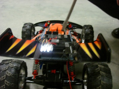
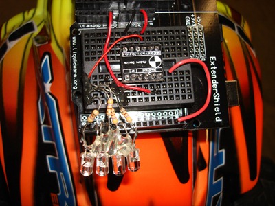
While this was excellent for the imaginary race car driver in my RC vehicle, this actually made it harder to detect high-g’s, well, simply because all the impact was absorbed! I originally had the CrashDuino rig mounted on the spoiler, but because the spoiler was attached separately (and on similarly bumper-like plastic), I had to move the rig closer to the point of contact on the car. I used a double-sided foam adhesive to stick the shields onto the plastic chassis.

DSC08285 CrashDuino Testing 

Step 5: Crash!

Here’s a couple more snapshots of the finished rig with the CrashDuino on the car:
And here’s a video of the second trial, with the Crash Test Sensor mounted on the front chassis:

I’ll be working on a digital version that reads out this info in real time, maybe with the TouchShield Slide. Paul’s got the Crash Test Sensor posted over at the Modern Device shop.

Now if I could figure out a way to mount it to a rocket… :)

Friday, February 19, 2010

Introducing the Compass Module: 5 ways to find your way

The Compass Module is the latest joint project stemming from collaborative engineering between Liquidware and Modern Device.
On the bus ride from New York to Washington DC, it occurred to me how (relatively) easy it is to find our way from one place to another, regardless of distance. There’s a well designated interstate highway system, filled with signs and rest stops where I can easily find out exactly where I am.
Most drivers are privy to state-of-the-art GPS navigation systems that read directions aloud, in real time, like a captain who simply knows it all. As a passenger, I had my iPhone, which allows me to triangulate my location with impressive accuracy via cellular signals and cell tower positions. In fact, it even had line by line walking directions (it would take me almost 3 days) and a course automatically charted out for me in a matter of seconds.
photo
I couldn’t help wondering how people traveled and *explored* in a time when not everything was clearly, accurately, and dynamically charted. Roads were probably not well labeled, if at all, and traveling across an ocean when you thought the world was flat was probably an endeavor filled with uncertainty.
Even today, navigation is a much bigger deal at sea, where there are no roads, no landmarks, no signs, and no cell phone signals. And if for some reason my vessel is hit by an electromagnetic pulse, I’ll be left with nothing but Pencil, Paper, and Stars.
 pencilpaperstars
1. Macgyver’s compass
Without an actual compass handy, Macgyver might default to a tried and true 4th grade science experiment: making your own compass. The premise is simple: run one side of a magnet over a thin piece of metal (like a needle) several times, always in the same direction. This magnetizes the needle, which when pushed through a piece of cork or straw and placed in water, will be free to float and spin to point north. Caveat: the temporary magnetism diminishes over time and this procedure needs to be repeated every couple days.
2. Following the North Star
Following the stars has been a way of navigation on land and at sea for ages. Polaris, also known as the North Star, is useful because it is bright and holds a constant position at the celestial pole. Its location at the pole means that its position in the sky isn’t impacted by the daily rotation of the earth, making it a perfect landmark on a clear night.
3. Dead Reckoning and the Traverse Board
Making use of pencil and paper, dead reckoning and the traverse board are a method of tracking position traveled. Starting from a known position, a chip log or weight would be attached to a reel of rope with knots tied in it at pre-defined spaces (hence the term nautical “knots”). The speed of the boat would then be tracked by counting the number of knots that had passed over an interval of time. Combined with recordings of orientation with a compass, a crew could track the path of the boat.
4. Using a watch as a “Sun Compass”
Yet another way to determine North, especially during the day, was to hold a watch with the hour hand facing the sun. Bisecting the angle between 12 and the current hour creates a North-South line – the further of which is North.
Make a Compass with the Sun and Time
5. Use an Arduino and a Compass ModuleSONY DSCComing back into the digital world, here’s the Compass Module for the Arduino. Like the Temp Sensor, it comes as a kit with either 4-pin male or stack-through headers that sit directly on the Arduino analog pins A2-A5. The compass module library is included in the latest release of the Antipasto Arduino IDE, which has updates for the Temp Sensor library as well. To get started, I simply installed the updated IDE and ran the Arduino compass library to start getting directional heading readouts from serial.
SONY DSC DSC08151
The Compass also communicates over the I2C protocol, and the data pin is bidirectional. In fact, multiple sensor modules can be stacked to communicate over the same analog pins on the Arduino, which I’ll write up soon.
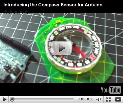
I took a video comparing the Compass Module with an analog compass, and lined both up for a quick demo:
Paul’s posted the Compass Module over at the Modern Device shop. In the meantime, I’m planning to do a couple more projects with the compass module next week, and I’m open to any thoughts or suggestions – jhuynh at gmail

Tuesday, February 16, 2010

My Overclocked, Liquid Cooled Arduino

Sometimes I just get this idea in my head, and no matter how stupid or impractical it may be, I'm not going to stop until it's done. Talking about Open Source Hardware theory, economics, and strategy so much recently is making my head explode with ideas, so I figured it was time for a gratuitous display of silly engineering. And with that, I'm quite pleased to present the world's first overclocked, liquid cooled Arduino :-)

This is a picture of the Arduino completely submerged under Eco-Earth FluidXP Non-Conductive coolant:


This is a shot of me holding up the Arduino just slightly out of the coolant, which I chilled by putting in the freezer for about 20 minutes, and also keeping it chilled while transporting it with a cold compress:


The overclocking part wasn't so bad, but the problem with overclocking the Arduino is that once you swap out the crystals or tamper with the oscillator circuit in general, you can't really program the Arduino with code any more. So I downloaded the simplest sketch I could think of, the Blink sketch. That's the one that blinks on and off every half second.

The normal Arduino is a 16 MHz chip. Mine runs at a little over 32 MHz, and is a Duemilanove. Here's a little video of the "behind the scenes" of how I soldered the new crystal in:


I was pretty nervous putting the Arduino into the liquid coolant for the first time, so I loaded it up with the TempSensor, and had it kick back readings to the computer as long as it could. You can't really tell from the video, but the liquid is freezing cold. The tips of my fingers were a bit numb after a few videos :-)


Anyway, these are probably my favorite pictures of the project - I uploaded some more pictures over at flickr:


:-)

Up and running on the TempSensor in less than 5 minutes

A bunch of people have written in to say they are enjoying the new TempSensor (ps thanks Rich for the bug fix in the code, now it works perfectly), and that makes me and Justin and Paul and Chris quite happy. It was an Open Source Hardware collaboration from start to finish, sharing schematics and code with each other. The goal was to create a set of sensors that were bullet proof.

Chris also spent a bunch of time coding up a special version of the Antipasto Arduino IDE (the Antipasto branch of the Arduino IDE), so that anyone who wants can literally pick up the TempSensor, wire it into analog ports 2, 3, 4 and 5, and be up and running in no time.

Here's proof:

Step 1: Download the Antipasto Arduino IDE

First download the Arduino IDE from here.

Install it and test out a simple Blink sketch on the Arduino to ensure that it works

Step 2: Connect the TempSensor to the Arduino

Insert the pins so that the TempSensor is facing downwards, off the bottom of the Arduino.

The TempSensor's pins should be placed into the Arduino's analog header, into pins 2, 3, 4, and 5.

Step 3: Load the Example Code


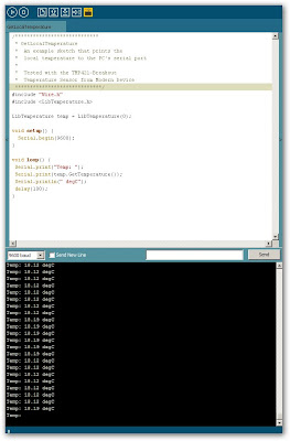
This is from the File->Examples->Library-LibTemperature->GetLocalTemperature menu option.


/****************************
* GetLocalTemperature
* An example sketch that prints the
* local temperature to the PC's serial port
*
* Tested with the TMP421-Breakout
* Temperature Sensor from Modern Device
*****************************/
#include "Wire.h"
#include

LibTemperature temp = LibTemperature(0);

void setup() {
Serial.begin(9600);
}

void loop() {
Serial.print("Temp: ");
Serial.print(temp.GetTemperature());
Serial.println(" degC");
delay(100);
}


Step 4: Hit Compile

This is the little triangular button.


Step 5: Download the Program to the Arduino

Select the right port, and the right Arduino board, naturally, and then press download.

Step 6: Open the Serial Terminal

And you'll see something like this:


Voila!

Wednesday, February 10, 2010

What Open Source Gadgets Can Learn From Corporate Toys

Over the past couple weeks, I’ve written about the concept of the open source hardware gadget: what it is, and why the world needs something like it. So I spent some time thinking about the “how” of creating open source gadgets. It appears to comprise two parts, planning, and executing, and I’ll try to outline the former here.

Looking across the variety of open source gadgets that have “made it”, so to speak, there are a couple trends that appear:

  1. For those with a specific purpose in mind, open source gadgets tend to fit the bill much better…though it’s a chicken and egg question due to post-purchase customizations
  2. Because it’s hardware, the notion of open source being “free as in speech” rather than “free as in beer” is prevalent. In fact, one might even argue that free as in speech is more valuable than free as in beer, and even worth a premium
  3. They seem to be almost always spearheaded by an ambitious, determined core group of engineers or hardware hackers (who have thought clearly about the value of open source)
  4. Project progress is usually slower/more likely to become vaporware than with corporate, commercial products, though those experience delays as well

It may make sense, then to take a look at the corporate counterparts for open source gadgets, and make comparisons to see what we can learn from how corporate products are created.

Organization in Open Source

Software development provides the most examples for drawing parallels. In open source, collaboration occurs with a shared repository for ongoing code development that’s decentralized (Github is a great example of such a tool), and there’s also a place where the projects are posted for public use like SourceForge. This virtual system works nicely only if there is someone who takes some responsibility for the project. It may not be explicit organization, but the “hub” is critical to organizing all the bits and pieces into cohesive updates. The reason, of course, is that for many projects, it’s a volunteer labor pool and a labor of love.

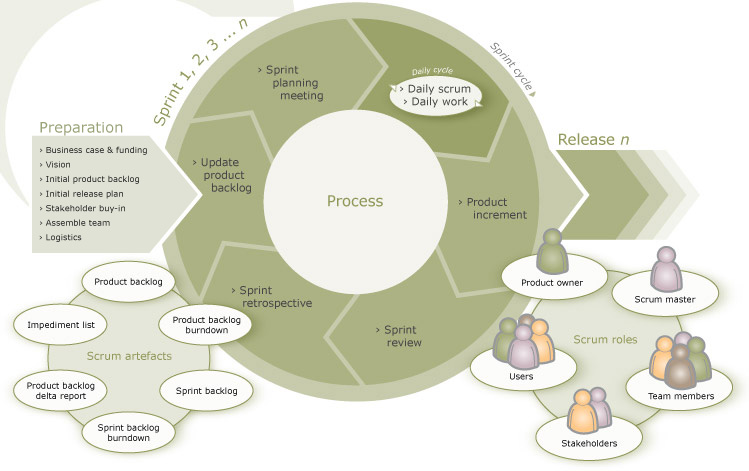
Commercially, however, software development teams are organized into many different schools of operation, like agile, scrum, or lean. The teams are budgeted and designated for the task, the product requirements are clearly specified, and a timeline is set in place. Development is far more centralized and predictable. Because product requirements are clearly specified, however, there’s less flexibility in customization, and the decisions of what to include and what not to include are far more gated than the forking style of open source software projects.

In hardware, the models don’t quite hold the same, largely because of the requirement of tangible prototyping. Within both corporate and open source hardware development, there’s a modularity or “chunking” of tasks that exists.

With open source hardware, though collaboration may occur, smaller teams tend to work together in a more direct or centralized way- be it passing schematics and gerbers back and forth. It’s less likely to open up a work-in-progress schematic or gerber to a larger group for small contributions; rather, these changes occur in turns and revisions of production, with each revision resulting in real tangible hardware being built.

Project Management and Likelihood of Success

This leads to a question of project management, and how different approaches may enhance or detract from its likelihood of completion.

Within a company, there are designated tasks, accountability, and typically much more time and financial resources devoted to a specific project plan, all essential when considering hardware development given non-trivial prototyping and production costs.

So despite delays between concept pieces at CES and an actual retailed device, there’s still a higher hit-rate of successful commercial gadgets to open source gadgets. That may not be a fair statement, though, since the open source hardware development model is relatively new and still materializing.

There’s a difference between having a group of engineers building a piece of hardware that is open source, and having it built in a decentralized way that derives its collaboration model from open source software.

Michael Arrington’s notorious Crunchpad project was launched under idealistic overtones of open source hardware, both of design and use. The call to “help us build it” signified a crowdsourced effort initiated at TechCrunch IT, similar to how a piece of open source software might be developed. While Arrington also suggested that the designs themselves might be open sourced after development, that’s consistent with a turn or revision-based model of hardware development. While Arrington gets credit for spearheading the idea and getting some prototypes together, what killed the Crunchpad project? After doing some research, a big part of it seems like the project was a little heavy on the pie-in-the-sky, and not enough on managing how to get the open source device out on the playing field.

phil-torrone-crunchpad

The Numbers Game: Costing, Pricing and Volume

There’s something beyond project management and development style that explains why there’s an iPad but still no Crunchpad (now JooJoo). And in its altered re-incarnation that is still in pre-order stage, it now feels like just another venture-backed, slick, company-built device…no longer with the open source hardware element.

The JooJoo concept

image

The iPad

image

There’s a populist expectation that open source is cheap and “dead simple”…if it’s built by the people for the people, it should also be people-pocket friendly. What many fail to see is that open source hardware can become expensive primarily because it lacks the economies of scale that a multi-billion dollar market leader like Apple can attain.

And Arrington made his case (and the news) by setting the bar very very low. Of course, as costs crept up, so did the expected price, from the original $200 to $300 to “$300-$400” to JooJoo’s $499. And it’s not open source. And it’s not hackable. So what’s the point?

All the while, Apple built what it built, closed source, which even at scale quantities, costs about an estimated $230. They never made any promises about costs or pricing (it ranges from $499 to a whopping $829!), but with resources in tow and devoid of undue, and somewhat contrived public price pressure, the iPad became a reality, largely on schedule.

Perhaps Ismael Ghalimi, who led the similar Redux Model 1 project, says it best:

“First, the announced pricing of $200 is pure wishful thinking. If an established company like Asus cannot sell a subnotebook for less than $300 while manufacturing millions of them, it’s unlikely that a custom-built tablet sporting a thinner case and expensive multi-touch screen could retail for anything less than $400…

This takes us back to the Redux Model 1, and the critical lessons we learned in developing its concept: bringing a new form factor to market is immensely difficult. It takes a lot of effort, costs a lot of money, and usually fails, for largely unforeseen reasons. At the end of the day, usability is the result of complex interactions between hardware, software, user interfaces, and you won’t know whether your design works or not until it’s done and millions (or tens, or even hundreds of them) have been spent.”

And in light of the Crunchpad failure, his words, written within days of the project’s launch, carry an echo of clairvoyance. It may seem like deja vu, but most likely a case of Arrington not being aware of the experiences of others.

Not to suggest that open source hardware should then be exceptionally overpriced and enclosed in typical Apple design, but making the price a focal point too early in the project may be a bad idea.

After all, it doesn’t matter how much the device costs, how much it is sold for, or even whether it’s open source, if it’s never built.

Monday, February 8, 2010

Introducing the Arduino Temp Sensor

The Temp Sensor marks the first (of many!) joint projects coming out of an engineering collaboration between Liquidware and Modern Device.

Modern_Device banner copy


Long before I saw Al Gore’s Inconvenient Truth, I used to come home from school and watch Captain Planet and the Planeteers, and I like to think that I got my environmentalist outlook at quite an early age.

For those who missed out, the story actually focuses on the five young Planeteers who are literally out to save the world from the reckless damage humans on the environment. Only when the Planeteers couldn’t take care of business would they then summon Captain Planet himself.

The Planeteers came from 5 different continents, and each represented a natural “element”. Not quite elements like Uranium or Cobalt, but what are known as “classical elements”: Earth, Wind, Fire, and Water. The fifth planeteer, Ma-Ti, represented Heart, which I assume is a spiritual quality of living things that separates the organic from the inorganic.

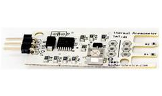
So when I talked with Paul over at Modern Device about his Wind Sensor, or as some would say, thermal anenometer (try saying that three times fast!), we started to think about what other neat sensors we could make.imageThat’s where the Planeteers come in. The jury is still out on an “Earth Sensor” (maybe an earthquake detector?), so after a Wind Sensor should come a Fire Sensor, a.k.a. Temp Sensor.SONY DSC So I guess one could say that the Captain Planet group of sensors has arrived :-) While we’re on the topic of projects I did in the fourth grade, I’ll be starting a little biosphere project with some of the new sensors and an Arduino, and document the ideal conditions for plant growth in a New England winter. A totally  different take on the concept of artificial life, might I add.

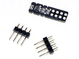
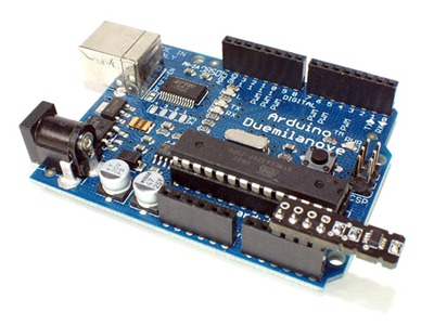
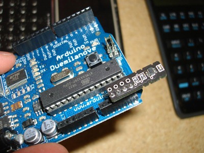
It has four pins: one for clock, one for data, +5V and ground, and it plugs right into the Arduino. The data pin is bidirectional, and communicates on the I2C protocol. Here’s a closeup of me holding the Arduino with the Temp Sensor mounted.

SONY DSCAnd here’s a quick video demo of the Temp Sensor in action. I used a cold compress to cool it down, and my fingers to warm it back up, and everything came out on the serial monitor:

I’ve added a new Arduino library to run the Temp Sensor directly as I did in this video, and I’ll do an “up and running” tutorial tomorrow, but this way, it’s easy to turn my Arduino into a thermometer instantly. Paul’s offering the Temp Sensor over at the Modern Device shop.

I’d be really interested in hearing some ideas for the Earth or “Heart” Sensor, or even some neat projects I could do as well – jhuynh at gmail…

Tuesday, February 2, 2010

Pyxis OS for Arduino Portable Megapalm: A Journey

Update: After getting several email requests, I’ve decided to provide an option for the Touchshield Slide to come pre-loaded with Thom’s Pyxis OS up and running out of the box.

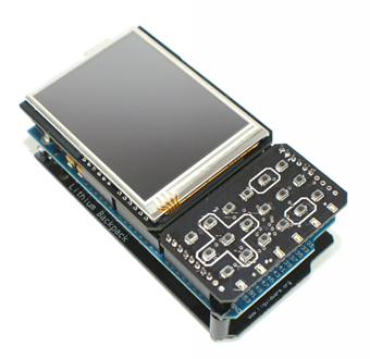
I’m also including this as a drop-down option for the Portable Megapalm, which Thom used in many of his demos, but the preload option can be added separately here. His compiler, Pyxis Studio, with 12 months of free updates, can be bundled on a snazzy 2GB USB stick as well.

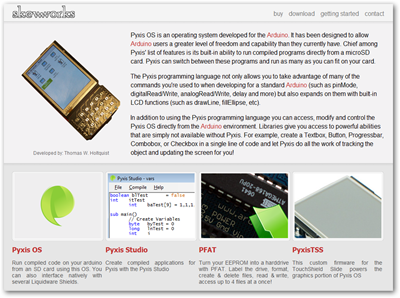
Thom just released Pyxis OS, which runs on the Arduino Portable Megapalm and a Pyxis Adapter Shield for the Mega that he built himself.

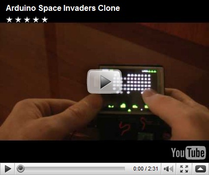
It’s been quite a journey though, and Pyxis pulls several projects together quite nicely. Over the summer, Thom launched a gaming system running on the TouchShield Slide, which he dubbed GAMEPAX. His first game, of course, was the classic Space Invaders game with a new twist – a tilt-based accelerometer control system.

Next came the graphics-intensive Super Mario clone for Arduino and Slide. To boost the framerate, Thom started hacking the Slide firmware, with some pretty impressive results.

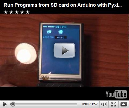
Later, Thom was able to hack together SD reader functionality on the Arduino + Slide, as well as a portrait mode. Throw in some SD/microSD reader function, an EEPROM file system, high and low level compiling (!)  and souped-up firmware for the ButtonPad and TouchShield Slide, not to mention months of power-coding, and the many threads of these projects came together as what’s been released as Pyxis OS, available at Thom’s page, www.skewworks.com, as well as the App Store.

Lest this appear to be devoid of hardware hacking, Thom’s also repackaged his project to create a Pyxis adapter shield compatible with the Arduino Mega. The adapter shield provides on-board access to DOSonChip SD card functionality.

Beyond Pyxis OS, Thom released the compiler as Pyxis Studio, which enables coding compiled applications in the PXE file format. Compiling assembly programs is free; compiling high-level programs into PXE costs a nominal amount to help offset hosting and development costs. Both will be soon be up available in the App Store as well.image

That’s not to mention the EEPROM file system project, now known as PFAT, and PyxisTSS, which contains the updated firmware and capabilities for Slide and Buttonpad.

It may seem like quite a deluge of cool projects, software, and hardware, but that’s because it is! More to come on the variety of new enhancements Pyxis brings to the Arduino platform. It’s definitely worth a look – www.skewworks.com

image

I’ll post up some “up and running” style walkthroughs for Pyxis next time – nice work, Thom!