Several folks had asked about ways they could wire some sensors or other components to tap into a grid of IXMs. So Chris and Paul worked with Dave to create the IXM Proto Cell.
The IXM Proto Cell contains a broad, solderable dev area that’s perfect for building analog RC circuits, and could interface with analog through an analog to I2C converter. The IXM Proto has a dual 7-pin interface along one edge that connects directly into a single face of any other IXM cell.
Each IXM digital pin is mapped out to a set of solder pads, and onboard 3.3V and 5V voltage regulators protect components from the IXM’s native 12V power rail. The remaining components equip the board for connecting circuits easily and driving outputs to the remainder of the IXM system. It’s also a handy debugger tool for reading out directly to various components, or to interface just about any part with the pins on an IXM cell – all within the same shape and form factor.
One way to think about the IXM Proto is that it’s the “wildcard” in the ecosystem. Anything goes, kind of like a DIY IXM cell.
I’ve posted it up at the Liquidware shop, and it’s available pre-assembled or as a solderable kit for the adventurous :)
A few months back, I reached out to a few folks in the Arduino community who were building some interesting shields, and picked up a few to add to the store. Well, the guys over at Asynclabs, who came up with the WiShield sent me a few more interesting pieces of hardware, which I’ve added to the Community section on the shop…
The first is the BlackWidow, or as some would call it, a “WiFi Arudino”, which uses a surface mount Atmega328 to make room for an onboard 802.11b WiFi module. I know people have been talking about it for a while, and it’s pretty neat to find one for less than the Arduino BT. Hooked up a Lithium Backpack and Slide, it could make quite a portable wireless access control panel...
For folks working on projects that need to fit in a smaller space, the YellowJacket packs everything onto a tiny, double-sided PCB, with a single 6-pin header to interface to a USB FTDI breakout board like the USB-BUB over at Modern Device: Breaking the wireless trend, the FlashShield is a solo prototyping shield that carries 16Mbit data flash for data logging and internet caching: And last but not least, WiShield 2.0 has arrived! This version of the WiShield comes with an external antenna, all SMT components, and a 16 Mbit dataflash built in.I’ve been surfing the Arduino forums and talking to a few people from the community about some new hardware. If there are modules I should add to the Community section of the shop, just let me know – jhuynh at gmail…
Yesterday was an exciting day to be in Cambridge. On the way in, Mike and I found ourselves in the middle of a massive motorcycle ride. Getting over to Ellery St, we noticed packs of lost-looking teenagers everywhere…each diligently clutching a crimson folder in one hand. That could only mean one thing: Visitas, Harvard’s latest official term for “pre-frosh weekend”. Nevertheless, there was only one place I wanted to be on such a gorgeous Saturday afternoon…
I brought the Gravitational RC Driving by Arduino project that Chris and I did last month. With all the tents and people walking around, it wasn’t really a good idea to have the car flying around. So I had it propped up on a couple Fastenal catalogs that would let the wheels keep spinning.
It was pretty neat to see kids getting into hardware and electronics so early, though. I certainly had no idea what an accelerometer or a touchscreen was when I was 7, but it seemed like they knew exactly what it was. I call it the “iPhone effect”, where everyone has a baseline understanding and expectation of how technology interacts with them, even if they can’t quite articulate it yet.
I found myself explaining what the Arduino was and how it was useful as a way to customize and rapidly prototype hardware really easily. The Arduino/Processing language is straightforward, most shield-based hardware is modular and “soldering-optional”, and communicating with ICs over dedicated, enumerated pins makes complex development quite manageable.
Mike and I also met a lot of interesting folks who work in the burgeoning Boston biotech scene. Some recognized the Arduino, but opted for embedded hardware with a little more horsepower like Gumstix and Beagleboard to do their prototyping.
My favorite question, though, was “What’s open source hardware?”, which led to some excellent conversations starting with: “Well, Ihopeyouhaveafewminutes” :)
Then Tim came by, picked up some modules and started telling his dad all about the Arduino projects. I was pretty inspired and almost asked him to take my spot at the table…Luckily, my friend Stephen came by to help out too, so I was able to wander around a bit. There were actually quite a few cool exhibits, including the guys right next to me from MITERS, who modded a shopping cart with a motor and steering wheel, and created a powerful, horn-like instrument with a couple 5-gallon buckets:
Pfizer had a couple booths as well, and they were quite the hit, making ice cream with liquid nitrogen. I wasn’t able to swim through the crowds to get up front, but from where I stood it seemed pretty cool (no pun intended):
The Cambridge Mini Maker Faire turned out wonderfully, and I’ll definitely be stopping by the other events at the Cambridge Science Festival. A special thanks to Chris Connors and Ellen Bluestein for getting me set up, and everyone who volunteered and stopped by to say hi, or play with some hardware!
For the folks who were asking, everything on the table is up over at the Liquidware shop, or Modern Device. I’m looking forward to the next Maker Faire already…
I was browsing the CSAIL event calendar at MIT, and noticed that next Thursday, there's an event on "reality-mining". It sounded like a pretty catchy idea, and after doing some digging, I realized that the concept of reality mining has a lot to do with opening up transparency into digital data about social interactions, etc. BUT! In a general sense, it also has to do with the process of understanding "machine-sensed environmental data."
Translation for mere mortals like me: "sensors"
:-)
The coolest part about reality-mining is the notion of visualizing the output of sensor type data in novel ways. So I figured I'd apply that concept to the Modern Device / Liquidware sensors. Starting with the Compass Sensor.
This is the code that gets uploaded onto the Arduino:
int val,x,y; int lastx = 0; int lasty = 0; char name[5];
void loop() {
if (Sensor.available()) { int value; value = Sensor.read(); x = lastx; y = lasty; if (strcmp ( Sensor.getName() , "1" )) x = value / 4; if (strcmp ( Sensor.getName() , "2" )) y = value / 4;
stroke(128); line(300,10,300,230);
if (x < x =" 0;"> 100) x = 100; if (y < y =" 0;"> 100) y = 100;
The code on the Arduino polls the Compass Module Sensor, and then sends the values to the TouchShield Slide using the HardwareSensor.h library that Chris built (available as a built-in library if you download the Arduino Antipasto IDE). Then the TouchShield Slide polls the Arduino's sensor values, and displays bar graphs. The result is nice, smooth-flowing, no-flickering bar graphs that show the values of the sensor in real time...
Here's a picture showing the bar graphs tilted to one side:
And this is probably my favorite picture of the bunch:
The latest sensor in the Liquidware-Modern Device collaboration is the Ambient Light Sensor. Paul’s uploaded it over at Modern Device, and I’ve put it up on the Liquidware shop as well.
In the spirit of being environmentally friendly, I’ve been trying to cut down on the amount of electricity I use. Well, the environment, and the fact that my electricity bill is really expensive.
I try to make it a habit to turn off my lights whenever I’m not home, but I’ll forget from time to time, and it would be nice to know. Or to be able to somehow measure whether it’s already (quantitatively) bright enough in the room, and I can dim my lights accordingly.
Something like a light meter is really ideal for it, because it could measure light accurately and automatically adjust brightness in my room, or let me shut it off if I find out that I’ve left the light on. Some phones already have this, and will dim the screen to conserve power in high ambient light. (Note: the pair of circles to the right are actually IR emitter-detectors that serve as proximity shut off the screen when the phone is held to the ear during a call – thanks Cyrozap!)With that in mind, AMBI, the ambient light sensor, came into being. The “AMBI” is a small board that carries a Sharp GA1A1S201WP surface-mount ambient light sensor.
The light sensor has a spectral response similar to that of the human eye, which means the sensor is highly accurate when used as the basis of an ambient light sensor, or camera exposure sensor. It’s also capable of digitally quantifying the brightness of a wide range of ambient light (3 to 55000 lux) in a very small form factor setup.
The AMBI's 3-pin interface mounts directly onto the analog pins on an Arduino, and tucked in really neatly under my TouchShield Slide.
The three pins are Ground, +5V and readout, which makes it very simple to interface to the analog pins. I’ve uploaded the PDF cheatsheet to help get things going over here. Anyway, I’ve started working on a couple fun projects, and I’ll be posting them up as tutorials over the next few days.
My time on this video is 5 minutes and 38 seconds.
The contest has simple rules:
-Beat my time by connecting 5 different types of sensors to the same Arduino one at a time. Only 1 Arduino Duemilanove or Diecimila. You can't pre-wire the sensors, you have to use them the way you got 'em. You can't use 5 of the same sensors. -If you do, you get 5 free sensors from Liquidware or Modern Device, and free shipping -If you already bought the sensors from Liquidware or Modern Device, I'll write you a check (none of that "store credit" stuff here) -If you're the first the break the 60 second threshold, you get a TouchShield Slide for free, also free shipping -"First" is determined by the date by which you uploaded a youtube video reply to this video
For each person who first breaks the 60 second mark, I will give out a free TouchShield Slide including Pyxis OS + Studio Pro ($194.93). That means 1 TouchShield Slide for each person who breaks the following marks:
5:00 4:00 - um maybe not possible? 3:00 - yeah right 2:00 - ha ha ha 1:00 - I will also buy you a beer if you are of legal age 0:30 - And dinner 0:00 - Dream on No negative times, no backwards running clocks, etc.
Yes, obviously there are multiple per household. Whoever came up with "only 1 per household" seriously pissed me off as a kid. If I collected that many proof of purchases from cereal box tops, you owe me 2 GI Joe action figures, General Mills. I will never forget that. General Mills, you ruined my childhood.
Moving right along.
This is a video of me putting together 5 sensors: a crash test sensor, a 3-axis accelerometer, a dual axis gyroscope, a temperature sensor, and an accelerometer in 5:38. The only things I had were:
I hate contests. I really hate when companies run contests that are like, "WIN THIS FOR FREE AND SUBMIT THIS FORM AND WIN A TRIP TO HAWAII YAYAYAYAYAYAYA XOXOXOXOXOX". That's lame. I always feel manipulated, and the contest ends up feeling gimmicky and stupid. Why am I wasting my time doing all this work just for the company to profit off of me?
That's why this is not one of those stupid contests. There's a point to this contest, and this is it:
Open Source Hardware and Physical Computing is done by people like me, DIY'ers who typically have day jobs, and do hobby projects at night and on weekends. I do my work in my own time, and I don't have time to fiddle around with spec sheets for hours just to get a sensor up and running.
DIY projects live and die by the clock. I call it the Race Against the Physical Computing Clock. If there's a portion of the project that takes too long, or is too complex, or requires me to read a 15 page PDF specification sheet in order to figure it out, the project will die.
The project won't get finished in one sitting, then it'll drag out over multiple weekends and weeks, months, it will collect dust. There are more DIY projects of mine unfinished on shelves than there are finished, and they all share one thing in common:
I'm too darn lazy to read technical whitepaper spec sheets.
I don't think I'm the only one, either. Paul and Chris shared my frustration, when it took us more than 19 minutes to get a sensor up and running that we had bought from Radio Shack. Apparently, someone at Radio Shack thinks it's an acceptable idea to sell sensors with bit timing diagrams and URL's where you have to download special drivers to get the sensor working. Are you kidding me? That kills the whole point of rapid prototyping DIY projects and physical computing.
Tom Igoe once told me, physical computing is about being able to see inside the case, open the box, you don't own it if you can't see and tinker inside. He called this the "glass box" principle.
I propose another principle: the "don't waste my time with spec sheets principle". I'll shorten it to the "spec sheet" principle. No DIYer should ever need to understand digital signal multi-wire chip select timing diagrams in order to get a sensor up and running. Ever. Over my dead body.
So Justin, Paul, Chris and I have made "sensor cheat sheets" and a new branch of the Arduino Antipasto IDE that reduce the amount of time required to get a given sensor up and running. We thought about the process that we, and other people we know, used to get a sensor communicating with Arduino.
We coined a metric, called, TBTSWWA, or "Time Before the Sensor Worked with Arduino". We clocked 4 different types of sensors, and averaged the time across the 4 of us. Paul and Chris are "advanced" users, I'm probably a "moderate", and Justin's like an "advanced beginner". I'm probably being generous to myself with that rating :-)
Here are our average results with 4 other commonly used accelerometer sensors, compared to the new Liquidware + Modern Device triple axis accelerometer. The y axis in the chart below is in seconds. The first sensor required soldering, and we had to assume that the soldering iron was warmed up. The next 3 sensors all required various degrees of hunting on the web for the source code that someone else had written for the sensor. That typically meant searching the Arduino forums or playground.
So what's the trick with the LW+MD (liquidware, modern device) sensors? Two things:
1) Sensors pinned out for 5 volts and clearly labeled, and pinned out in a minimal-footprint to make wiring logical and minimize the number of wire connections
2) Sensor cheat sheets which summarize everything you need to know to get the sensor up and running in 1 page
3 months ago, Paul from Modern Device, Chris from Liquidware, and I sat down at coffee in New Haven with a bunch of Arduinos and sensors from Sparkfun, Parallax, Radio Shack, Digikey, and Jameco and started hacking together some small fun projects using the sensors to measure the positions of our limbs and 3D objects.
It was surprisingly frustrating.
The problem was, in order to get a sensor working, you need 4 major things:
1) The sensor 2) A breakout board for the sensor 3) Wiring diagrams for how to power up the sensor 4) Code to get the sensor up and running
1 isn't hard to get, you can get sensors for all over the place. 2 isn't bad either, since Nate at Sparkfun does a really nice job with his breakout boards. But 3 is usually buried deep inside a PDF spec sheet written in China that usually looks a lot like the most technical thing you've ever seen. And 4 is a crapshot, and you have to cross your fingers and pray that someone else has ported the code.
So we figured that had to be a better way to do physical computing with sensors.
We promised ourselves we would spend the next 3 months achieving an "order of magnitude increase in time-based productivity with DIY physical computing sensors".
And this is the result of that work.
By the way, if you're curious, here are some "test" videos of me "training" for the 5:38 video shoot :-)
A lot of people have been writing to me the past week congratulating me on being in Make Magazine. First of all, thank you very very much... it's a big deal for me, because 1) it came out looking not so bad in real print (thanks to the guys and graphic designers at Make), 2) Make is a big deal, and 3) I'm only a couple pages away from Mr. Dyson's ad for his super duper vacuum cleaner...
Here's the front page of Make magazine for this month:
Here's the super duper vacuum cleaner ad:
And here's my ad!!!!!!!
The ad shows the TouchShield Slide, and 5 physical computing sensors that Paul from Modern Device and Chris and I collaborated on to develop. The goal of the sensors was to decrease the time and complexity of working with sensors by 1 order of magnitude. That meant that if it previously took 10 minutes to get a sensor up and running on the Arduino, Paul, Chris, and I wanted to make it work in 1 minute or less. I think it worked... but more in the next blog post...
There is no way I designed that ad by myself, so I have to thank my friend Kristoph from school who now works at one of the big design firms in NYC who helped me set up the picture, take the picture, layout the text, and format it. Justin and I then did the finishing touches on the picture and text.
Anyway, it's not everyday that I feel proud of a piece of art that I had a part in, and this ad was a pretty big milestone for me, so to I also put it up on the front page of Liquidware to celebrate :-)
I can't believe the picture actually came out looking half-way decent in print. I mean it's one thing to print it out 50 times on a photo printer and plaster it all over my wall... it's another thing to actually have it come out looking halfway decent :-)
Over the past several months, I’ve received quite a few questions on getting started with the Arduino and TouchShield Slide (Matt also did a nice summary last week), and some of the other hardware over at the Liquidware shop. So the next project on my list was to create a single, central place for folks to get started…
Whenever I bought hardware in the past, I would do one of two things: a) rely on my intuition to figure it all out, or b) look for a quick start guide to get me going.
Option A only worked about 35% of the time for me, but I suspect that most DIYers actually fare rather well with it, and perhaps it works 60 or 70% of the time.
Even so, Option B was never a bad thing to have. It was with that concept in mind that Matt and I wrote up the Sensor Cheatsheets. But from a ground level, something was still missing. In other words, if I had no idea what kind of hardware I just picked up, what do I do?
Besides telling people to give me a call, or send me a note, there’s now the Liquidware “Start” page, aptly located at:
I’ve compiled the latest software and hardware links, and included three sets of instructions for the most common things people ask me after they’ve bought their Portable MegaPalm or Starter Kits:
-How do I use Arduino with these shields and sensors? -How do I program the TouchShield Slide? -How do I upload images to the Slide?
There are no frills on this page, just steps and links to get from point A to point B. I’ll be updating it as the questions change, or as I add new features, and I’m hoping it will be a good roadmap for how to get going with new hardware, software, and resources :)
As promised, I’ve been doing a little spring cleaning by working my way through my list of “most frequent requests”. A few website and documentation updates are already up, and today it’s all about the Antipasto Arduino IDE. Feel free to let me know if there’s anything I should add– jhuynh at gmail
Several folks have been asking for a few features in the Antipasto IDE that bring some enhancements to the standard Arduino and Processing interface. Many an IDE generation (and update) later, Chris and I sat down, and decided it was time to roll up our sleeves and do some spring cleaning.
Based on a lot of the comments he and I received, some things were working better than others, and some new features were really becoming popular and needed to be integrated.
I’ve also created a dedicated download page hosted on the Liquidware website just for the Antipasto Arduino IDE. All future updates will be shared here, so there will be no need to look elsewhere or get mixed up with an older version.
The latest Antipasto Arduino IDE is labeled Arduino-0018-Antipasto-0041. This way, anyone who uses it will also know which version of the standard IDE Antipasto is synched up with. Without further ado…
After a few revisions of the Arduino and Processing IDEs, it was time to sync up on some bug fixes, and bring Antipasto’s enhancements to an interface more in line with what most folks were used to.
2. Better integration with Windows 7 (and 64-bit as well)
This is one I personally had trouble with. When I decided to cross the great “4 gigabytes of RAM” divide, I knew it was time to upgrade to 64-bit. I also heard some decent things about Windows 7, like “At least it’s not Vista”, so I decided to give it a try. But Windows 7 64-bit broke my Antipasto and Arduino IDE for some time, and I was running the IDE off an old laptop.
The good news is that this latest version of Antipasto should have most of those issues resolved :-)
3. Removed *.gdt file support
In the spirit of streamlining the latest Antipasto, Chris took out the gadget panel and *.gdt support. However, the extended reference panel is still included, and library/sample sketch selection adjusts automatically depending on the board selected.
4. Added HardwareSensor library for direct sensor to Slide interface
Some people who bought the Navigation Rig were using the accelerometer to interface with the TouchShield Slide. After a bit of coding, they suggested that it might make sense to have a library built in to make visualizing sensor data on the Slide quicker and easier.
This is another feature that’s been sitting on the to-do list, since image uploading is a critical function for most Slide users. Anyway, it’s now integrated with an example sketch. The Image Uploader’s drag-and-drop functionality is built into the Antipasto interface, and works nicely with the Slide.
These are the biggest changes to the latest Antipasto Arduino IDE, and it can be downloaded here:
Of course, there were lots of little behind the scenes fixes throughout, so if it wasn’t working before, this new update is worth a try. Let me know how it works out – jhuynh at gmail or send me a note on the Ask page. More updates and tutorials to come this week…
It’s about that time of year that even frosty New England starts to get some sun. It’s also the time of year when school starts to wind down with finals and senior design projects.
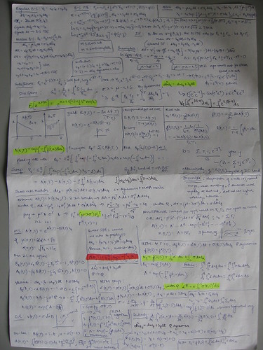
Every once in a while, especially in the more quantitative classes, the professor would allow students to bring in a one page, single-sided cheat sheet created from textbook formulas and class notes. Too bad magnifying glasses weren’t allowed too :)
Inspired by the idea, and a few keen suggestions (thanks Keith!) Matt and I wrote up some starter “cheatsheets” to get folks started with some of the new Liquidware+Modern Device sensors.
Compared to the scribbles and highlights above, it’s actually quite minimalistic. The idea, of course, is to include the basic, no-frills info to get the sensor module wired to the Arduino and printing outputs to serial.
On a similar note, I’ve been doing a little bit of spring cleaning to organize a lot of the resources that have accumulated over the past few months. A lot of it is just putting to use great ideas from some of the questions and comments that I’ve received from several folks, which I’ll post more about that in the upcoming week…
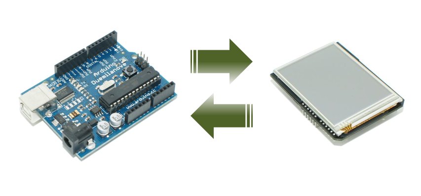
Recently, I've been getting a lot of questions from folks asking about the TouchShield Slide. What is it, how does it work, and how does in talk to the Arduino?
So here's a quick run-down for people who are just finding it for the first time:
What is it?
The TouchShield Slide is a shield for the Arduino. It has a really bright OLED screen on the front, and it has a touch-screen pad on top of it, that allows you to create interfaces, and physical computing GUI's with it. Chris and I made the TouchShield Slide about a year ago to experiment with GUI's and gadgets, after being inspired by the large number of emerging modular gadget platforms that were springing up, and deciding that it was time to upgrade the TouchShield Stealth, which was the original DIY OLED screen we built a while back. At the time, Chris and I thought, modularity is pretty cool, why not bring it to the Arduino platform?
Naturally, there are a few undocumented easter eggs hidden on the TouchShield Slide too :-)
How does it work?
The TouchShield Slide snaps on top of the Arduino, Duemilanove or Mega, by slotting into the pins on the digital side, analog side, and power port. The power pins provide voltage to the shield, and power the OLED screen. The Digital pins allow the Arduino to send and receive serial commands to and from the TouchShield Slide. This is helpful, for instance, if you have a sensor connected to the Arduino, and you wanted to send the values of the sensor to the TouchShield Slide to display as bar graphs.
Controlling OLED's is not an easy thing to do, and in fact, if the Arduino were to try to control an OLED directly by itself, it would basically use up all of the programming capability of the Arduino, and leave no computation left over to do anything else (like poll sensors or blink LEDs or read switches). So to ease the load on the Arduino, the TouchShield Slide has it's own processor on the backside that basically acts as a graphics processor. It takes over all the heavy duty processing from the Arduino, and leaves the Arduino untouched (or at least very minimally touched).
How do I program it?
The first thing to understand is that you have to program the TouchShield Slide separately from the Arduino. That means, you place the TouchShield Slide on top of the Arduino, and then you download the IDE for Windows here or for Mac here.
This IDE is called the "Antipasto Arduino IDE", and is specially updated from the original Arduino IDE to allow code to be written and programmed and downloaded to the TouchShield Slide. Here is a sample "hello world" program for the TouchShield Slide: void setup() { background(0,0,0); //this paints the whole background black stroke(0,0,255); //the outline of the next shape I draw will be blue fill(0,0,255); //the inside fill of the next shape I draw will be blue }
void loop() { gettouch(); //find out where a finger is touching ellipse(mouseX, mouseY, 3, 3); // draw an ellipse(x, y, width, height) }
After you compile the code above (which is a lot like how you program code for the Arduino, except you just have to select "TouchShield Slide" from the boards menu), and plug in the USB port from the computer to the Arduino, you then have to press the tiny little button on the side of the TouchShield Slide, which "resets" the shield, and puts it into a mode of waiting for code to come from the PC. The you press the "program" or "download" button in the Arduino IDE, and the code gets downloaded to the Slide. When it's done downloading, the TouchShield automatically resets itself, and the program you wrote starts running.
How does it talk to the Arduino?
The TouchShield Slide has a set of functions built in to it that make it easy to send data back and forth between the TouchShield and the Arduino.
A quick side note, iamshadowlord has written a nice tutorial on this, which goes into more depth, over here. (Thanks!) For advanced programmers, this is a good example of how to send data back and forth!
So I've tried to simplify it for beginners a little bit by making a simple "HardwareSensor" library that now dramatically simplifies the interface between the Arduino and the TouchShield Slide. It's called HardwareSensor, because I got so many emails from people asking, "How do I send sensor data from the Arduino to the TouchShield Slide?". This is how (here's the link for the reference docs): On the Arduino, you put this code: void setup() { Sensor.begin(19200); }
void loop() { int value = analogRead(5); Sensor.print("accel", value); }
And on the TouchShield Slide, you put this code: void setup() { Sensor.begin(19200); background(0); }
void loop() { if (Sensor.available()) { int value;
value = Sensor.read(); //get the sensor value text(value, 50, 10); // print the value to the screen text(Sensor.getName(), 10, 10); // print the name to the screen } }
In the coming days, I'm going to be writing a LOT more about the HardwareSensor library, and how you can use it to make physical computing GUI and graphical displays... here goes nothing!


 Luckily, my friend Stephen came by to help out too, so I was able to wander around a bit. There were actually quite a few cool exhibits, including the guys right next to me from
 ![Maker Faire MITers[1]](http://lh3.ggpht.com/_1uSuqk4teiU/S9SwMfX5JhI/AAAAAAAAAh4/-KbtahU1Og0/Maker%20Faire%20MITers%5B1%5D%5B2%5D.jpg?imgmax=800 "Maker Faire MITers[1]")