I was reading through Phil's recent article profiling tons of different open source projects over at the Open Source hardware guide at Make Blog, and it got me thinking... what is open source, really? It reminded me of a recent conversation I had with Tom Igoe about why Open Source hardware is so much harder to define than software was and how he and the rest of the Arduino team wrestled with it. And that time I had dinner with Chris, Mike and Paul Badger , and talked about how Paul thinks about "Open Source" with his students.
Phil's article also reminded me of conversations I had with Karim Lakhani about the topic of open source collaboration, networks, and peer production. In the software world, it's relatively straightforward, because source code is infinitely replicable, easy to share, can be edited by almost anyone (willing to learn the programming language and owning a PC). But on the hardware side, it's not easy to define academically, which is no help to guys like me actually trying to make open source stuff!
Coincidentally, I just gave a presentation to some students up in Boston from MIT and Harvard (and a few stragglers) who were interested in Open Source hardware. The forum was dedicated to open source concepts and topics, and how to get started with your own open source project. I decided to meet with some professors ahead of time, to try to get a more theoretical approach to the problem. In those discussions, I got some interesting responses and of course some difficult questions I hadn't thought of before:
-Is hardware "open source" because you can change it, make it yourself, expand it, or customize it? What actions can I do with an open source device that I can't do with a proprietary one?
-What precisely about the hardware needs to be open? PCB traces? Etching chemicals and fiber boards? Transistors and gate arrays? How low down the hardware stack does it need to go before you call it open?
-How do you compare two different projects to each other? Can you ever say one project is more or less open than another? Is "open sourceness" a binary attribute, or can it be a spectrum?
-What is the goal of open source hardware, and why do we need more of it?
-Where does someone go to get started making their own open source hardware?
-If someone builds a project, what decisions do they make that leads them to open source vs. proprietary vs. closed?
-What the analogy of "source" mean to hardware? Is it figurative or literal? Is it the firmware, is it the logic inside a discrete IC? Is it the synthesized VHDL core in a microprocessor?
-Can something ever be open source if it includes proprietary, closed components like professionally built microprocessors? Is "open sourceness" in hardware a recursive attribute, like it is in GNU software?
So my first conclusion was: there's a lot more to think about here than I first thought - I knew it was hard, but this is a lot to bite off for one presentation. My second observation was: it's easy to overlook a lot of what makes something really feel "open". I think I went into the discussions thinking something could be either "open source" or not, but I left with the feeling that open source was more fuzzy than I'd originally thought. In fact, someone recommended that I read up on some of Richard Stallman's original posts on open source, where he ran into many of these same questions - maybe he'd have some answers.
In any case, I wrapped up all of my thoughts, and put together a presentation, which I've uploaded here for anyone to read through. I tried to capture the different opinions about open source hardware, and profiled a few projects I'm involved with, in order to propose a definition of what "open source hardware" really means. This it the first time I've used slideshare, so I hope it works!
Thanks a lot for all the feedback and ideas! And let me know if you want a copy of the presentation...
Sunday, November 30, 2008
Wednesday, November 26, 2008
Introducing the 8-bit embedded TurkeyShield
I'm always looking out for new ways to add more shields and components to my Arduino, and this felt like a natural (and festive) experiment, so I gave it a shot: it's an Arduino, Potentiometer (for user input), accelerometer (to know it's bearings), and compass (so the turkey's always facing due north), Lithium Backpack (for mobility of course), and TouchShield Stealth (for output) wired through a fairly large turkey :)
I've just uploaded all the pictures over here on Flickr.
In the DIY spirit, of course, here's a 5-step guide to making your own 8-bit embedded turkey:
1) Buy and cook a turkey (thanks for the help, Mike)

2) Cut a square hole in one side for the TouchShield, and a small round hole in the other side for the potentiometer

3) Insert the potentiometer knob and TouchShield into the turkey (trying carefully not to short any exposed wires through the turkey, since it's technically conductive):


I didn't believe it either, but I tested it: turkeys are conductive - this is why I had to do the next step:

4) Place the Lithium Backpack in a plastic baggie, with the wires coming out the top. It's a little risky putting an exposed lithium battery cell up against conductive turkey meat, so this is an important step:

5) Upload program code to read the accelerometer and compass from Parallax:

Of course it's open source, so the code is pasted at the bottom of the post
Here's a video of the full "circuit" in action:
Here's the source code to run on the Arduino (thanks, kiilo!):
#include
#define RXPIN 3
#define TXPIN 2
AFSoftSerial mySerial = AFSoftSerial(RXPIN, TXPIN);
unsigned char x=0;
/*
/////////////////////////////////
Htachi HM55B Compass
parallax (#)
AUTHOR: kiilo kiilo@kiilo.org
License: http://creativecommons.org/licenses/by-nc-sa/2.5/ch/
http://parallax.com/Store/Microcontrollers/BASICStampModules/tabid/134/txtSearch/hm55b/List/1/ProductID/98/Default.aspx?SortField=ProductName%2cProductName
http://sage.medienkunst.ch/tiki-index.php?page=HowTo_Arduino_Parallax_HM55B_Kompass
http://arduino.cc/playground/HM55B
/////////////////////////////////
*/
#include // (no semicolon)
//// VARS
byte CLK_pin = 5;
byte EN_pin = 4;
byte DIO_pin = 6;
int X_Data = 0;
int Y_Data = 0;
long angle;
//// FUNCTIONS
void ShiftOut(int Value, int BitsCount) {
for(int i = BitsCount; i >= 0; i--) {
digitalWrite(CLK_pin, LOW);
if ((Value & 1 << i) == ( 1 << i)) {
digitalWrite(DIO_pin, HIGH);
//Serial.print("1");
}
else {
digitalWrite(DIO_pin, LOW);
//Serial.print("0");
}
digitalWrite(CLK_pin, HIGH);
delayMicroseconds(1);
}
//Serial.print(" ");
}
int ShiftIn(int BitsCount) {
int ShiftIn_result;
ShiftIn_result = 0;
pinMode(DIO_pin, INPUT);
for(int i = BitsCount; i >= 0; i--) {
digitalWrite(CLK_pin, HIGH);
delayMicroseconds(1);
if (digitalRead(DIO_pin) == HIGH) {
ShiftIn_result = (ShiftIn_result << 1) + 1;
//Serial.print("x");
}
else {
ShiftIn_result = (ShiftIn_result << 1) + 0;
//Serial.print("_");
}
digitalWrite(CLK_pin, LOW);
delayMicroseconds(1);
}
//Serial.print(":");
// below is difficult to understand:
// if bit 11 is Set the value is negative
// the representation of negative values you
// have to add B11111000 in the upper Byte of
// the integer.
// see: http://en.wikipedia.org/wiki/Two%27s_complement
if ((ShiftIn_result & 1 << 11) == 1 << 11) {
ShiftIn_result = (B11111000 << 8) | ShiftIn_result;
}
return ShiftIn_result;
}
void HM55B_Reset() {
pinMode(DIO_pin, OUTPUT);
digitalWrite(EN_pin, LOW);
ShiftOut(B0000, 3);
digitalWrite(EN_pin, HIGH);
}
void HM55B_StartMeasurementCommand() {
pinMode(DIO_pin, OUTPUT);
digitalWrite(EN_pin, LOW);
ShiftOut(B1000, 3);
digitalWrite(EN_pin, HIGH);
}
int HM55B_ReadCommand() {
int result = 0;
pinMode(DIO_pin, OUTPUT);
digitalWrite(EN_pin, LOW);
ShiftOut(B1100, 3);
result = ShiftIn(3);
return result;
}
//Pin definitions
int xaccPin = 7;
int yaccPin = 8;
//Global variables
long xacc = 0;
long yacc = 0;
long readAcceleration(int axe){
int count = 0;
long accel = 0;
int value = 0;
value = digitalRead(axe);
while(value == HIGH) { // Loop until pin reads a low
value = digitalRead(axe);
}
while(value == LOW) { // Loop until pin reads a high
value = digitalRead(axe);
}
while(value == HIGH) { // Loop until pin reads a low and count
value = digitalRead(axe);
count = count + 1;
}
//accel = abs(8 * (count * 18 / 10 - 500)); //this was the original function
accel = count;
return accel;
}
void setup() {
Serial.begin(9600);
pinMode(EN_pin, OUTPUT);
pinMode(CLK_pin, OUTPUT);
pinMode(DIO_pin, INPUT);
pinMode(xaccPin, INPUT);
pinMode(yaccPin, INPUT);
HM55B_Reset();
mySerial.begin(9600);
while(mySerial.read() != 'U');
}
unsigned int a, xa, ya;
void loop() {
HM55B_StartMeasurementCommand(); // necessary!!
delay(40); // the data is 40ms later ready
HM55B_ReadCommand();
//Serial.print(HM55B_ReadCommand()); // read data and print Status
//Serial.print(" ");
X_Data = ShiftIn(11); // Field strength in X
Y_Data = ShiftIn(11); // and Y direction
//Serial.print(X_Data); // print X strength
//Serial.print(" ");
//Serial.print(Y_Data); // print Y strength
//Serial.print(" ");
digitalWrite(EN_pin, HIGH); // ok deselect chip
angle = 180+ (180 * (atan2(-1 * Y_Data , X_Data) / M_PI)); // angle is atan( -y/x) !!!
//Grab the accelerometer readings:
xacc = readAcceleration(xaccPin); //reads and represents acceleration X
yacc = readAcceleration(yaccPin); //reads and represents acceleration Y
a = angle;
xa = xacc;
ya = yacc;
//Print the output to the serial port:
Serial.print(a); // print angle
Serial.print(" ");
Serial.print(xa);
Serial.print(" ");
Serial.print(ya);
Serial.println("");
x=0;
while (x < 6)
{
serial_sendAnalog(x);
x++;
}
delay(10);
x=0;
while(x< 14)
{
serial_sendDigital(x);
x++;
}
delay(100);
}
void serial_sendDigital(unsigned char digitalPin)
{
if ( (digitalPin <> 13) )
return;
mySerial.print((unsigned char)1);
delay(2);
}
void serial_sendAnalog(unsigned char analogPin)
{
unsigned char lowByte, highByte;
unsigned int val;
/* Pin number range check */
if (analogPin > 6)
return;
/* Get the value */
//val = analogRead(analogPin);
val =10;
if (analogPin ==1) {
val = (2.5*a);
}
if (analogPin ==2) {
val = xa-700;
}
if (analogPin ==3) {
val = ya-700;
}
if (analogPin ==0) {
val = analogRead(0);
}
if (analogPin ==4) {
val = analogRead(4);
}
if (analogPin ==5) {
val = analogRead(5);
}
/* Separate the value into 2 bytes */
lowByte = (unsigned char)val;
highByte = (unsigned char)(val >> 8);
/* Send the high byte */
mySerial.print(highByte);
/* Write delay */
delay(1);
/* Send the low byte */
mySerial.print(lowByte);
/* Write delay */
delay(1);
}
And here's the code that runs on the TouchShield:
COLOR green = { 0, 255, 0 };
COLOR blue = {0,0,255};
COLOR yellow = {255,255,0};
COLOR BLACK = {0,0,0};
COLOR grey = {0x77,0x77,0x77};
COLOR red = {255,0,0};
COLOR black = {0,0,0};
unsigned int analogValues[6];
unsigned char digitalValues[10];
unsigned char x;
void setup()
{
drawBackground();
delay(8000);
Serial.begin(9600);
/* The sync character */
Serial.print('U');
}
void drawBackground()
{
}
void loop()
{
/* Read the analog values */
for (x=0; x< 6; x++)
analogValues[x] = (Serial.read() << 8) + Serial.read();
for (x=0; x< 10; x++)
digitalValues[x] = Serial.read();
/* Redraw the analog values */
updateAnalog();
updateDigital();
}
void updateDigital()
{
unsigned char x;
char out[6];
green.red = 0;
green.green = 255;
for(x=0; x<10; x++)
{
//if (digitalValues[x])
// lcd_puts("H", digitalRect.left+2, digitalRect.bottom-8-(x*10), red, BLACK);
//else
// lcd_puts("L", digitalRect.left+2, digitalRect.bottom-8-(x*10), green, BLACK);
}
}
void updateAnalog()
{
unsigned char x;
char out[9];
float f[6];
f[0] = ((float)analogValues[0]/1024.0) * 120.0;
f[1] = ((float)analogValues[1]/1024.0) * 120.0;
f[2] = ((float)analogValues[2]/1024.0) * 120.0;
f[3] = ((float)analogValues[3]/1024.0) * 120.0;
f[4] = ((float)analogValues[4]/1024.0) * 120.0;
f[5] = ((float)analogValues[5]/1024.0) * 120.0;
/*
f[1] = 64.0;
f[2] = 64.0;
f[3] = 64.0;
f[4] = 64.0;
f[5] = 64.0;
*/
//lcd_clearScreen( black);
drawhbar(1,10+19*0, 14, 120, (int)f[0]);
drawhbar(1,10+19*1, 14, 120, (int)f[1]);
drawhbar(1,10+19*2, 14, 120, (int)f[2]);
drawhbar(1,10+19*3, 14, 120, (int)f[3]);
drawhbar(1,10+19*4, 14, 120, (int)f[4]);
drawhbar(1,10+19*5, 14, 120, (int)f[5]);
/*
//lcd_rectangle(1,120-(int)f[0],1+14,120, red, red);
//lcd_rectangle(1,1,1+14,120-(int)f[0], black, black);
drawvbar(10+19*0, 120, 120, 14, (int)f[0]);
drawvbar(10+19*1, 120, 120, 14, (int)f[1]);
drawvbar(10+19*2, 120, 120, 14, (int)f[2]);
drawvbar(10+19*3, 120, 120, 14, (int)f[3]);
drawvbar(10+19*4, 120, 120, 14, (int)f[4]);
drawvbar(10+19*5, 120, 120, 14, (int)f[5]);
*/
for(x=0; x<6; x++)
{
//lcd_rectangle(1,2+12*x,f[x],12+12*x, red, red);
//lcd_rectangle(f[x],2+12*x,120,12+12*x, black, black);
//drawhbar(1,12*x, 12, 128, (int)f[x]);
//dtostrf(f[x],4,3,out);
//out[5]=0;
//lcd_puts(out, 10, 10+(x*10), green, BLACK);
delay(10);
}
}
void drawhbar(int x, int y, int h, int w, int val) {
lcd_rectangle(x,y,val,y+h, red, red);
lcd_rectangle(x+val,y,w,y+h, black, black);
}
void drawvbar(int x, int y, int h, int w, int val) {
lcd_rectangle(x,y-val,x+w,y, red, red);
lcd_rectangle(x,y-h,x+w,y-val, black, black);
}
I've just uploaded all the pictures over here on Flickr.
In the DIY spirit, of course, here's a 5-step guide to making your own 8-bit embedded turkey:
1) Buy and cook a turkey (thanks for the help, Mike)

2) Cut a square hole in one side for the TouchShield, and a small round hole in the other side for the potentiometer

3) Insert the potentiometer knob and TouchShield into the turkey (trying carefully not to short any exposed wires through the turkey, since it's technically conductive):


I didn't believe it either, but I tested it: turkeys are conductive - this is why I had to do the next step:

4) Place the Lithium Backpack in a plastic baggie, with the wires coming out the top. It's a little risky putting an exposed lithium battery cell up against conductive turkey meat, so this is an important step:

5) Upload program code to read the accelerometer and compass from Parallax:

Of course it's open source, so the code is pasted at the bottom of the post
Here's a video of the full "circuit" in action:
Here's the source code to run on the Arduino (thanks, kiilo!):
#include
#define RXPIN 3
#define TXPIN 2
AFSoftSerial mySerial = AFSoftSerial(RXPIN, TXPIN);
unsigned char x=0;
/*
/////////////////////////////////
Htachi HM55B Compass
parallax (#)
AUTHOR: kiilo kiilo@kiilo.org
License: http://creativecommons.org/licenses/by-nc-sa/2.5/ch/
http://parallax.com/Store/Microcontrollers/BASICStampModules/tabid/134/txtSearch/hm55b/List/1/ProductID/98/Default.aspx?SortField=ProductName%2cProductName
http://sage.medienkunst.ch/tiki-index.php?page=HowTo_Arduino_Parallax_HM55B_Kompass
http://arduino.cc/playground/HM55B
/////////////////////////////////
*/
#include
//// VARS
byte CLK_pin = 5;
byte EN_pin = 4;
byte DIO_pin = 6;
int X_Data = 0;
int Y_Data = 0;
long angle;
//// FUNCTIONS
void ShiftOut(int Value, int BitsCount) {
for(int i = BitsCount; i >= 0; i--) {
digitalWrite(CLK_pin, LOW);
if ((Value & 1 << i) == ( 1 << i)) {
digitalWrite(DIO_pin, HIGH);
//Serial.print("1");
}
else {
digitalWrite(DIO_pin, LOW);
//Serial.print("0");
}
digitalWrite(CLK_pin, HIGH);
delayMicroseconds(1);
}
//Serial.print(" ");
}
int ShiftIn(int BitsCount) {
int ShiftIn_result;
ShiftIn_result = 0;
pinMode(DIO_pin, INPUT);
for(int i = BitsCount; i >= 0; i--) {
digitalWrite(CLK_pin, HIGH);
delayMicroseconds(1);
if (digitalRead(DIO_pin) == HIGH) {
ShiftIn_result = (ShiftIn_result << 1) + 1;
//Serial.print("x");
}
else {
ShiftIn_result = (ShiftIn_result << 1) + 0;
//Serial.print("_");
}
digitalWrite(CLK_pin, LOW);
delayMicroseconds(1);
}
//Serial.print(":");
// below is difficult to understand:
// if bit 11 is Set the value is negative
// the representation of negative values you
// have to add B11111000 in the upper Byte of
// the integer.
// see: http://en.wikipedia.org/wiki/Two%27s_complement
if ((ShiftIn_result & 1 << 11) == 1 << 11) {
ShiftIn_result = (B11111000 << 8) | ShiftIn_result;
}
return ShiftIn_result;
}
void HM55B_Reset() {
pinMode(DIO_pin, OUTPUT);
digitalWrite(EN_pin, LOW);
ShiftOut(B0000, 3);
digitalWrite(EN_pin, HIGH);
}
void HM55B_StartMeasurementCommand() {
pinMode(DIO_pin, OUTPUT);
digitalWrite(EN_pin, LOW);
ShiftOut(B1000, 3);
digitalWrite(EN_pin, HIGH);
}
int HM55B_ReadCommand() {
int result = 0;
pinMode(DIO_pin, OUTPUT);
digitalWrite(EN_pin, LOW);
ShiftOut(B1100, 3);
result = ShiftIn(3);
return result;
}
//Pin definitions
int xaccPin = 7;
int yaccPin = 8;
//Global variables
long xacc = 0;
long yacc = 0;
long readAcceleration(int axe){
int count = 0;
long accel = 0;
int value = 0;
value = digitalRead(axe);
while(value == HIGH) { // Loop until pin reads a low
value = digitalRead(axe);
}
while(value == LOW) { // Loop until pin reads a high
value = digitalRead(axe);
}
while(value == HIGH) { // Loop until pin reads a low and count
value = digitalRead(axe);
count = count + 1;
}
//accel = abs(8 * (count * 18 / 10 - 500)); //this was the original function
accel = count;
return accel;
}
void setup() {
Serial.begin(9600);
pinMode(EN_pin, OUTPUT);
pinMode(CLK_pin, OUTPUT);
pinMode(DIO_pin, INPUT);
pinMode(xaccPin, INPUT);
pinMode(yaccPin, INPUT);
HM55B_Reset();
mySerial.begin(9600);
while(mySerial.read() != 'U');
}
unsigned int a, xa, ya;
void loop() {
HM55B_StartMeasurementCommand(); // necessary!!
delay(40); // the data is 40ms later ready
HM55B_ReadCommand();
//Serial.print(HM55B_ReadCommand()); // read data and print Status
//Serial.print(" ");
X_Data = ShiftIn(11); // Field strength in X
Y_Data = ShiftIn(11); // and Y direction
//Serial.print(X_Data); // print X strength
//Serial.print(" ");
//Serial.print(Y_Data); // print Y strength
//Serial.print(" ");
digitalWrite(EN_pin, HIGH); // ok deselect chip
angle = 180+ (180 * (atan2(-1 * Y_Data , X_Data) / M_PI)); // angle is atan( -y/x) !!!
//Grab the accelerometer readings:
xacc = readAcceleration(xaccPin); //reads and represents acceleration X
yacc = readAcceleration(yaccPin); //reads and represents acceleration Y
a = angle;
xa = xacc;
ya = yacc;
//Print the output to the serial port:
Serial.print(a); // print angle
Serial.print(" ");
Serial.print(xa);
Serial.print(" ");
Serial.print(ya);
Serial.println("");
x=0;
while (x < 6)
{
serial_sendAnalog(x);
x++;
}
delay(10);
x=0;
while(x< 14)
{
serial_sendDigital(x);
x++;
}
delay(100);
}
void serial_sendDigital(unsigned char digitalPin)
{
if ( (digitalPin <> 13) )
return;
mySerial.print((unsigned char)1);
delay(2);
}
void serial_sendAnalog(unsigned char analogPin)
{
unsigned char lowByte, highByte;
unsigned int val;
/* Pin number range check */
if (analogPin > 6)
return;
/* Get the value */
//val = analogRead(analogPin);
val =10;
if (analogPin ==1) {
val = (2.5*a);
}
if (analogPin ==2) {
val = xa-700;
}
if (analogPin ==3) {
val = ya-700;
}
if (analogPin ==0) {
val = analogRead(0);
}
if (analogPin ==4) {
val = analogRead(4);
}
if (analogPin ==5) {
val = analogRead(5);
}
/* Separate the value into 2 bytes */
lowByte = (unsigned char)val;
highByte = (unsigned char)(val >> 8);
/* Send the high byte */
mySerial.print(highByte);
/* Write delay */
delay(1);
/* Send the low byte */
mySerial.print(lowByte);
/* Write delay */
delay(1);
}
And here's the code that runs on the TouchShield:
COLOR green = { 0, 255, 0 };
COLOR blue = {0,0,255};
COLOR yellow = {255,255,0};
COLOR BLACK = {0,0,0};
COLOR grey = {0x77,0x77,0x77};
COLOR red = {255,0,0};
COLOR black = {0,0,0};
unsigned int analogValues[6];
unsigned char digitalValues[10];
unsigned char x;
void setup()
{
drawBackground();
delay(8000);
Serial.begin(9600);
/* The sync character */
Serial.print('U');
}
void drawBackground()
{
}
void loop()
{
/* Read the analog values */
for (x=0; x< 6; x++)
analogValues[x] = (Serial.read() << 8) + Serial.read();
for (x=0; x< 10; x++)
digitalValues[x] = Serial.read();
/* Redraw the analog values */
updateAnalog();
updateDigital();
}
void updateDigital()
{
unsigned char x;
char out[6];
green.red = 0;
green.green = 255;
for(x=0; x<10; x++)
{
//if (digitalValues[x])
// lcd_puts("H", digitalRect.left+2, digitalRect.bottom-8-(x*10), red, BLACK);
//else
// lcd_puts("L", digitalRect.left+2, digitalRect.bottom-8-(x*10), green, BLACK);
}
}
void updateAnalog()
{
unsigned char x;
char out[9];
float f[6];
f[0] = ((float)analogValues[0]/1024.0) * 120.0;
f[1] = ((float)analogValues[1]/1024.0) * 120.0;
f[2] = ((float)analogValues[2]/1024.0) * 120.0;
f[3] = ((float)analogValues[3]/1024.0) * 120.0;
f[4] = ((float)analogValues[4]/1024.0) * 120.0;
f[5] = ((float)analogValues[5]/1024.0) * 120.0;
/*
f[1] = 64.0;
f[2] = 64.0;
f[3] = 64.0;
f[4] = 64.0;
f[5] = 64.0;
*/
//lcd_clearScreen( black);
drawhbar(1,10+19*0, 14, 120, (int)f[0]);
drawhbar(1,10+19*1, 14, 120, (int)f[1]);
drawhbar(1,10+19*2, 14, 120, (int)f[2]);
drawhbar(1,10+19*3, 14, 120, (int)f[3]);
drawhbar(1,10+19*4, 14, 120, (int)f[4]);
drawhbar(1,10+19*5, 14, 120, (int)f[5]);
/*
//lcd_rectangle(1,120-(int)f[0],1+14,120, red, red);
//lcd_rectangle(1,1,1+14,120-(int)f[0], black, black);
drawvbar(10+19*0, 120, 120, 14, (int)f[0]);
drawvbar(10+19*1, 120, 120, 14, (int)f[1]);
drawvbar(10+19*2, 120, 120, 14, (int)f[2]);
drawvbar(10+19*3, 120, 120, 14, (int)f[3]);
drawvbar(10+19*4, 120, 120, 14, (int)f[4]);
drawvbar(10+19*5, 120, 120, 14, (int)f[5]);
*/
for(x=0; x<6; x++)
{
//lcd_rectangle(1,2+12*x,f[x],12+12*x, red, red);
//lcd_rectangle(f[x],2+12*x,120,12+12*x, black, black);
//drawhbar(1,12*x, 12, 128, (int)f[x]);
//dtostrf(f[x],4,3,out);
//out[5]=0;
//lcd_puts(out, 10, 10+(x*10), green, BLACK);
delay(10);
}
}
void drawhbar(int x, int y, int h, int w, int val) {
lcd_rectangle(x,y,val,y+h, red, red);
lcd_rectangle(x+val,y,w,y+h, black, black);
}
void drawvbar(int x, int y, int h, int w, int val) {
lcd_rectangle(x,y-val,x+w,y, red, red);
lcd_rectangle(x,y-h,x+w,y-val, black, black);
}
Tuesday, November 11, 2008
Getting ready to take a "vacation"...
I'm getting ready to take a 2 week "vacation" from my day job to do a bunch of coding and prototyping, and especially to build a few more games. I've got a backlog of project ideas that I've sketched up, and it finally was a convenient time to take some time off.
Anyway, I'm going to be in a code-happy mood for the next couple weeks, and I'm going to shoot for an ambitious target: more than 2000 lines of Arduino code per week (I estimated that based on the size of BitDJ, which took a few weeks to write). I'm hoping that will translate to a number of games, some new uses for the backpacks, and a few pet projects - like recreating an HP12C financial calculator in reverse polish on the TouchShield, and maybe even the old arcade game, Tron.
In the meantime, if you had any code you were thinking of writing and might have needed help on, just send me an email sometime in the next couple of weeks, and I'll do my best to help. Thanks, and get ready for some code and projects :)
Monday, November 10, 2008
Random Stuff
To demonstrate a few *random* functions added to the TouchShield's core, I made a simple application.

I've uploaded the code for it over at the project page
I'll be making a new TouchShield core release soon with updates and bug fixes. Thanks for the great feedback!
Chris

I've uploaded the code for it over at the project page
I'll be making a new TouchShield core release soon with updates and bug fixes. Thanks for the great feedback!
Chris
Back in Black! Introducing the Lithium Backpack Stealth
*Edit*Thanks for the comments on the new lithium backpacks... I've assembled a handful of them with Matt and Mike, and they're ready to ship. I've updated the description over at www.liquidware.com. Thanks a lot, Justin *Edit*
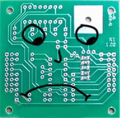
When the Lithium Backpacks ran out, it was a good chance to upgrade a few parts of the design to increase load when needed, add a heftier reverse current protector, and some new battery shapes. They'll be over at the liquidware.com site, under Lithium Backpack Stealth:
Here's a picture of hicap, "Big brother" and locap, "little brother":

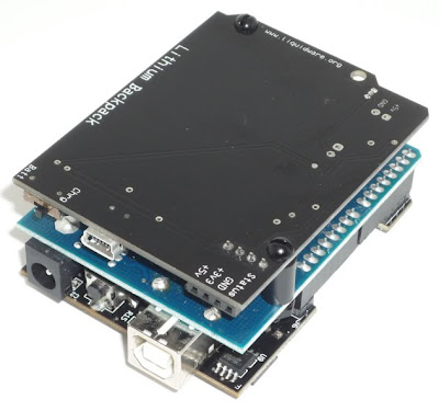
Lithium BackPack Stealth and other components in the kits:

Thanks a lot!
Justin and Matt
Figure 1. Old version: sad Green PCB

When the Lithium Backpacks ran out, it was a good chance to upgrade a few parts of the design to increase load when needed, add a heftier reverse current protector, and some new battery shapes. They'll be over at the liquidware.com site, under Lithium Backpack Stealth:
Here's a picture of hicap, "Big brother" and locap, "little brother":


Lithium BackPack Stealth and other components in the kits:

Thanks a lot!
Justin and Matt
Wednesday, November 5, 2008
InputShield How 2
I just built a data sheet for the InputShield...

http://www.liquidware.com/
It's only four pages, but it should have all the information needed to use the joy stick and buttons. This will definitely act as a good cheat sheet if anyone wants to replicate Matt's Open Source Game boy project.

The InputShield has 2 modes to control the output and input pins. This feature allows the user to control 2 InputShields from the same Arduino I/O board.
 If you have any questions, shoot me an e-mail.
-Mike
http://www.liquidware.com/
It's only four pages, but it should have all the information needed to use the joy stick and buttons. This will definitely act as a good cheat sheet if anyone wants to replicate Matt's Open Source Game boy project.
The InputShield has 2 modes to control the output and input pins. This feature allows the user to control 2 InputShields from the same Arduino I/O board.
If you have any questions, shoot me an e-mail.-Mike
Subscribe to:
Posts (Atom)