Parts:
- 2 x Arduinos
- 2 x XBee Shields
- 2 x Solid Core Wire
- 2 x USB Type-B Cables
- 2 x Computers (I used 1 vista and 1 xp)
 I will now go through the painful preliminary steps I did to setup my xbee network.
- Download X-CTU from Digi's website (And installed it... yeah, I installed the updates)
- Repeat for both computers
- Put both Arduinos in Reset

- Attach the XBee Shield to the Arduino
- Attach a USB cable from one arduino to Computer "A"
- Attach the other USB cable to the other arduino and Computer "B"
- Open X-CTU on Computer A
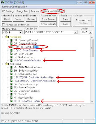
- Go to the "Modem Configuration" tab... set the Modem: XBEE to "XB24-B" AND set the Function Set to "ZNET 2.5 ROUTER/END DEVICE AT"

- Next is the Networking and Addressing Parameters...
- PAN ID = 1111
- Scan Channels = 15 (not sure if this is even needed)
- Channel Verification = 0 (also not sure if this is even needed)
- Destination Address High = 13A200 (I found this out by typing "AT" commands into a terminal program... first type in "+++" the xbee will return an "OK" you are now in command mode... if you type "ATSH" then "
" (enter), the xbee will give you it's own high address (source address) ) 
- Destination Address Low = 403E2502 (I found this out by typing "AT" commands into a terminal program)
- Broadcast Radius = 0
- Click the "Write" button on the Modem Configuration tab and wait for the XBee to program
- If some funny error comes up... click the button on the xbee shield and try to program it again
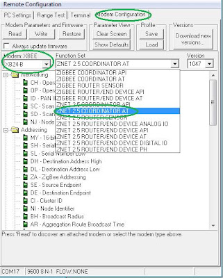
- Go to the "Modem Configuration" tab on computer B... set the Modem: XBEE to "XB24-B" AND set the Function Set to "ZNET 2.5 COORDINATOR AT"
- Next is the Networking and Addressing Parameters for the XBee attached to computer B...
- PAN ID = 1111
- Scan Channels = 15 (not sure if this is even needed)
- Channel Verification = 0 (also not sure if this is even needed)
- Destination Address High = 13A200 (I found this out by typing "AT" commands into a terminal program... first type in "+++" the xbee will return an "OK" you are now in command mode... if you type "ATSH" then "" (enter), the xbee will give you it's own high address (source address) )
- Destination Address Low = 404A4FC4 (I found this out by typing "AT" commands into a terminal program)
- Broadcast Radius = 0
- Click the "Write" button on the Modem Configuration tab and wait for the XBee to program
- If some funny error comes up... click the button on the xbee shield and try to program it again
- whew... now both devices are configured properly... open the X-CTU terminal tab of each computer... type and see the characters fly from pc to pc
I would like to thank the help of the following people...
The Digi Corporation: X-CTU, XBee Data Sheet, Gilbert (866) 765-9885 (thanks for calling back and sorry I missed your call)
The Arduino XBee Page, the Arduino Forum (Thanks Brad B).
Thanks Carin from Humboldt
Thanks Limor... for your tutorial... Gilbert just posted on the Arduino forum and your tutorial seems solid!
I can't wait to actually use these for projects now.
11 comments:
I can't believe you actually figured out how to get this working... I've had two of these for months and months, and haven't found a single tutorial or sample code anywhere! Can't wait to try it out...
I ran across your blog and thought I could help simplify your procedure a little. First, it may not be necessary to use two separate computers to do this. The board should create a virtual COM port on your PC. Simply create another and then you can run two instances of X-CTU.
Step 11 is only necessary to force the radio onto a particular frequency. If left alone, the module will choose a frequency to operate on, on its own.
Step 12 is unnecessary.
When setting the DH and DL parameters, set them to match the SH and SL parameters of the radio you wish to communicate with (and vice versa). If using the X-CTU, in the Modem Configuration tab, clicking the Read button will display all the parameters in your radio (including the SH and SL), then simply point and click to change parameter values.
Steps 15 and 25 are unnecessary.
That being said, the XBee radios that you are using are ZigBee radios, used to create a mesh network. Digi has several other radios in the XBee family (drop in replaceable with the ones you have) which will communicate to each other out of the box, and not need any configuration.
Help is needed. We are trying to setup an Xbee Pro(USB explorer) to communicate to another Xbee Pro(shield), which is connected to the arduino. How can we set up to read data to the USB explorer to the shield with only one of everything that you have
thanks ur information
it very useful
Small business website design
You do not need X-CTU to program the XBee, you can do it just through hyperterminal.
I programmed it using AT commands, on my own design of the "XBee Shield"
I am not sure about API yet, still trying to figure that whole thing out.
Between this tutorial and Gilberts comment I FINALLY got these talking to each other.
Thanks for the help!
Used 1 arduino and 1 usb explorer and works fine to let arduino speak to matlab running on my PC.
Hi thanks for your post. I have managed to configure 2 XBees, both connected to the PC through a USB explorer. But at the terminal page, there's no flying of characters from pc to pc as you described it. i do see the TX led on one XBee lighting up, but that;s all. am i missing something?
Hi everyone,
I've been trying to follow the posted steps but whenever I try to write the parameters to the XBee modem using X-CTU I get the following messages:
Getting modem type....OK
Programming modem...Detected baud rate difference.
Make sure PC and modem baud rate is set correctly
Lost communication with modem
Write Parameters...Failed
Do you think you could help me? What would be the correct baud rate in that case? Are there any other serial port parameters I should set?
Cheers,
Leandro
Hi everyone,
I've been trying to follow the posted steps but whenever I try to write the parameters to the XBee modem using X-CTU I get the following messages:
Getting modem type....OK
Programming modem...Detected baud rate difference.
Make sure PC and modem baud rate is set correctly
Lost communication with modem
Write Parameters...Failed
Do you think you could help me? What would be the correct baud rate in that case?
Cheers,
Leandro
Great tutorial !
One thing that had me troubled for a while was you didn't clearly describe to retrieve the destination address from the OTHER Xbee and input that in the first Xbee. Can be too obvious. But good to clearly state in the text so the people will not make mistakes. I got it to work when I started thinking. Your article was key to getting this to work equipped only with two XB24-B XBees and two UartsBee cards.
I can add; I configured the two XBees using two UartsBee adapter cards on which I installed the XBees, two USB cables connected to the USB ports of a MacBook Pro with OSX, running the VirtualBox VM where I run Windows 7 where I executed X-CTU.
I ran two instances of X-CTU, one for each of the two serial ports. This was a neat way of pairing the two bees. By typing text in the Terminal windows of one X-CTU program you could monitor the text arriving in the Terminal window of the other X-CTU instance.
Post a Comment