The latest sensor module from the Liquidware and Modern Device collaboration is the 3-Axis Accelerometer.
Last week, Chris and I used the Crash Test Sensor on a radio-controlled car and measured the crash impact in a classic analog way: with a bunch of white LEDs.
This week, the 3-axis accelerometer was ready, so I wanted to create a gravitational based control…kinda like the WiiDuino, except rather than using the WiiMote for sensors, build my own gravitational controller from scratch, and use it to control something else.
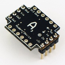

This 3-axis accelerometer module uses the MMA7260QT chip from Freescale, but after frying one too many a “low-voltage” IC, I decided to build in some 5V protection to keep it safe from my Arduino. Paul’s posted it over on Modern Device.
The RC car had a two-part remote control- a knob that controlled left-right steering of the front wheels, and then a throttle trigger that controlled the speed and direction of the car (forward/stop/reverse).
It actually worked out nicely that the controls were separated into left-right for steering, and forward-backward for direction. This way, I could tilt my gravitational drive rig left or right to steer (motion in the Y-axis), while tilting toward or away from me controlled the throttle (motion in the Z-axis).
The gravitational drive rig consisted (primarily) of an Arduino Duemilanove, a DoubleWide ExtenderShield with a mini-protoboard attached, a Lithium Backpack, and the 3-axis accelerometer module.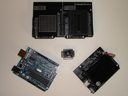 The Arduino and accelerometer parts were going to be the sensors, but to control the RC car, I still needed to tap into the existing remote, especially since I wasn’t about to generate my own radio frequencies!
So I cracked open the remote…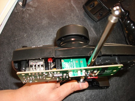 …and started looking around to see how the controls might work
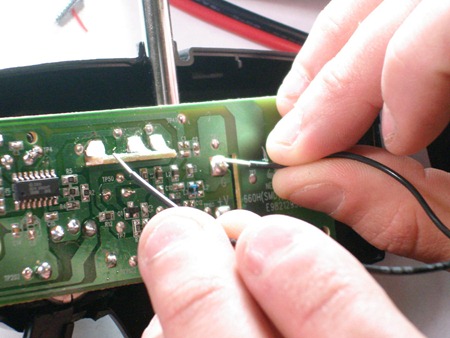 It was actually a little more complicated than expected, and I measured some of the voltages across non-descript leads to figure out what was actually being modified with each control. So the Arduino and accelerometer’s outputs needed to be connected to the correct contact points to transmit accurate instructions to the car.
I’ll save the science and the circuit diagrams for a “making of” post in the next couple days, but it took a few tries and adding some switches to get the right voltages and resistances at each contact point.
Here’s what the final rig looked like: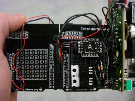 The accelerometer’s Yout and Zout are wired into the Arduino, which then relayed instructions to the contacts on the remote. The whole gravitational drive remote was powered off a Lithium Backpack.
 Controlling it this way was actually pretty intuitive, and my friend Matt got pretty good at driving it. I took a video of him taking the car for a spin:
And just for kicks, I challenged Matt to drive it through a little course of cones, like they do in the car commercials:
I’m still thinking of cool things to do with a 3-axis accelerometer, so I’m open to any ideas. In the meantime, I’ll scribble some notes on how I got the Arduino and remote talking for a “behind the scenes” post :-)

1 comment:
that is so sick... nice work!
Post a Comment