Step 1 - Get your BeagleBoard
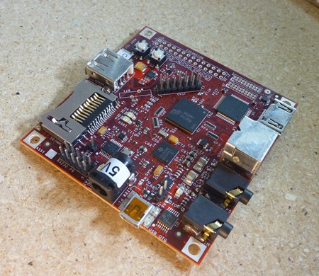
This is the first and most obvious step – just take out the BeagleBoard, and place it on the table, prepared for a brief cosmetic surgical procedure (no, nothing like Heidi from the Hills, much simpler and less obvious!)
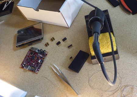
Step 2 - Unpack everything from the box and organize it
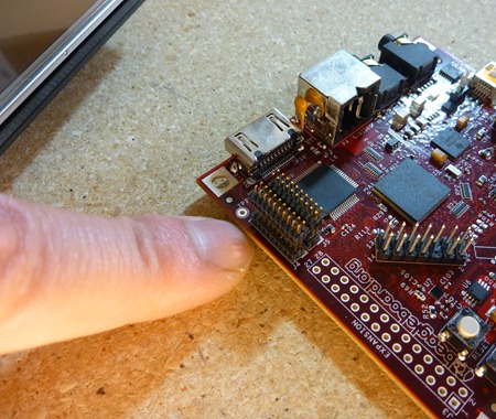
There are 4 individual headers that need to get soldered onto the BeagleBoard. Why? Because the BeagleTouch requires a lot of IO pins to transmit all the high speed data to and from the BeagleBoard. Essentially, the BeagleTouch becomes a handheld, symbiotic, integral screen element, a lot like when in Avatar when the Na’vi form a symbiotic interdependence with the other creatures of… nevermind.
Step 3 - Place the little headers in J4 and J5 and solder them in
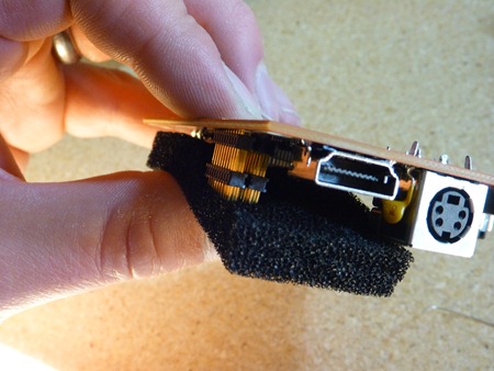
To do this, I used a piece of black anti-static foam to secure the two mini-headers relative to the big RS-232 header. It stayed in place well, and I made sure that that the headers were aligned parallel so that they could snap into the appropriate sockets on the BeagleTouch. This is the hardest part of the process, because you have to make sure the headers are parallel.
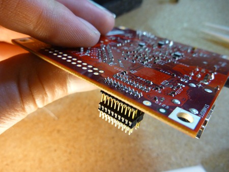
EDIT: Actually, it’s just as easy to simply follow Step 4, and place the headers into the BeagleBoard, and then snap the BeagleTouch onto the loose headers, then flip the whole thing on its back, and solder them up. Thanks Jim.
Step 4 - Place the two other headers, and mount the BeagleTouch
Once the little guys are in, the bigger headers are easy - I used the BeagleTouch itself as a jig to hold the headers in place. 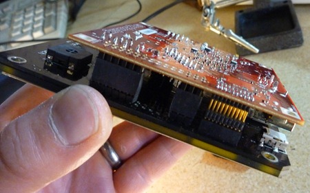
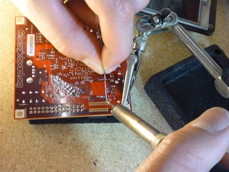
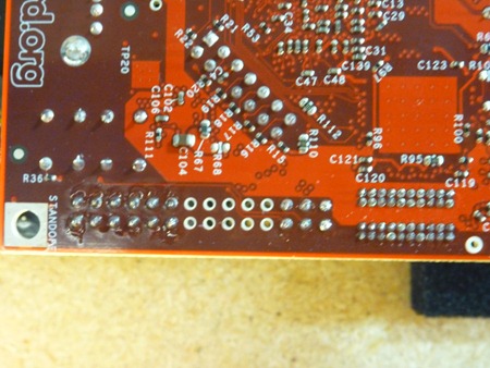
Step 5 - Solder the large headers onto the Beagle Board
By now, if you’ve figured out how to solder in the tiny ones, these are a cinch. The reason I did these second, is because I knew that the little ones would require more focus, and I have really bad ADD and if I had done it the other way around, I probably would have lost patience and gotten sloppy toward the end. At least this way, if I got sloppy toward the end, it was with the big honking headers that take more solder…
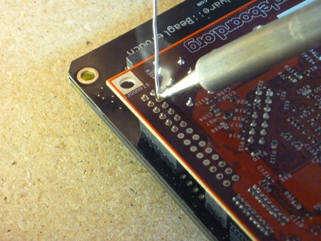
Afterward, just do a quick visual inspection to make sure that each pin stands alone, and that there isn’t any solder bridging over two pins.
Optional: Step 6 - Insert 1 single header to the remaining IO connector, bend them, and solder them
If you want to do physical computing with the BeagleBoard, you probably want to make the general purpose connector IO easy to get to when the BeagleTouch is stacked on top. Sooooo… Justin gave me a 1x5 female header (which is in the kit), so I could solder it in, then bend it out to the side. The result is a nifty little way to get access to digital IO on the BeagleBoard… although of course this step isn’t absolutely necessary just to get the BeagleTouch up and running.
Step 7 - Mount the BeagleTouch, insert SD card, and power it on
Then I inserted in the Liquidware BeagleBoard Linux boot SD card, and plugged it in using a 5V wall adapter.
Step 8 – If you’re lazy….
If you don’t want to do any of the steps above, for an extra $20, I’ll solder everything for you, and make sure it works. I don’t know, some people really like doing it themselves, other people (e.g. guys with more programming background), don’t want to do it, and aren’t as confident with a soldering iron, and so they would prefer to pay someone else to do it.
On the Liquidware shop, I’ve added an option to the page for me to solder the headers for you…

1 comment:
Is there any possibility I can get a 7" or 10" version of the beagle touch ??? If yes, how much will it cost and how long will it take to ship ??
Post a Comment